Views: 0 Author: Zisheng Electric Publish Time: 2026-10-08 Origin: Zisheng Electric
A transformer Buchholz relay interface review should connect the mechanical arrangement, alarm and trip wiring, and release evidence into one controlled record. A relay certificate alone cannot show that the installed pipework matches the approved arrangement or that each contact reaches the intended destination. Those boundaries deserve attention before factory release, especially when the conservator or connecting pipe will be removed for transport.
This guide proposes a coordination framework for transformer buyers, EPC engineers and inspection teams. It concerns conservator-type liquid-immersed transformers equipped with a specified Buchholz relay. It is not a universal installation procedure, protection setting schedule or authorization to energize. The approved project design and the exact relay manufacturer's instructions govern the installation and testing.
Begin with the transformer equipment tag, relay manufacturer and model, purchase specification and drawing revisions. Identify the protected liquid compartment and the associated conservator connection. A drawing for the main tank should not be assumed to describe a separate tap-changer protection arrangement. List any accessories, remote gas sampling equipment or additional indications that belong to the ordered package.
The scope also needs a release boundary. A factory mechanical inspection, a factory contact test and a site trip-chain test answer different questions. Record which activities will be completed with the transformer assembled, which will be repeated after transport, and which depend on equipment outside the transformer supplier's scope. An unsigned assumption between two contractors should become an explicit interface action.
For a broader package, place this review within the project's EPC power solution interface register. Give every open item an owner, required document and closure stage. This makes the relay review part of equipment delivery rather than an isolated accessory checklist.
Schneider Electric's Buchholz relay explanation describes the typical distinction between gas-accumulation alarm and oil-displacement trip functions on conservator transformers. That functional description does not determine the project's final annunciation, interlocking or breaker logic. Confirm the actual contact arrangement and approved protection schematic for the ordered device.
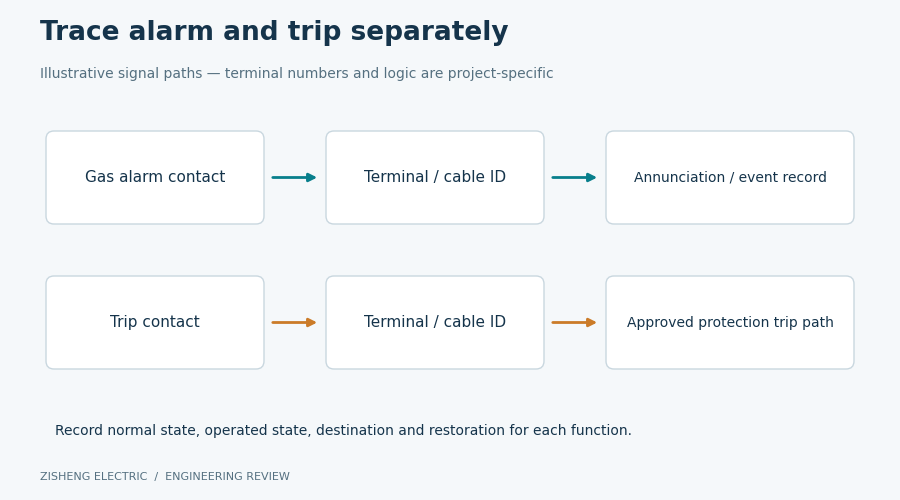
Use separate identifiers for each required signal. A drawing note reading only “Buchholz connected” is too broad for a reviewer to trace an individual alarm or trip path. The schedule should show the device contact, local terminal, marshalling terminal, outgoing cable reference and destination. Where a connection is outside factory scope, clearly mark that boundary instead of leaving a blank that looks like a completed check.
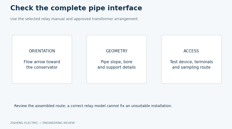
The mechanical review should compare the assembly drawing with the actual tank-to-conservator connection. Record the relay orientation, connection identification, installed geometry and available access. Include photographs with enough context to show the relay and adjacent pipe sections; an isolated close-up of its nameplate does not establish how the assembly is installed.
The EMB operating instructions for Buchholz relays address flow direction, installation geometry, flange loading and transport locking. Their requirements are model-dependent. Use the instructions applicable to the supplied relay rather than copying a pipe slope, support spacing or mounting tolerance from another project.
Review geometry and accessibility against the approved drawing and supplied relay instructions.
A proposed inspection record can reference the relevant drawing detail beside each measured or visually checked feature. This is more useful than a collection of unreferenced photographs. If the final arrangement differs from the approved drawing, describe the difference and obtain the responsible designer's disposition. A neat assembly does not, on its own, demonstrate conformity to the intended hydraulic path.
Review access for the inspections and service activities specified by the manufacturer. Consider the final location of guards, cable trays, handrails and adjacent accessories. An inspection performed before those items are installed may not establish final accessibility. Any reliance on removable structures or special access equipment should be included in the operating and maintenance information supplied to the owner.
Pipe alignment and support questions should remain with the competent mechanical designer and installation team. Do not resolve a mismatch by forcing flanges together or changing support positions without a controlled instruction. The record should identify the affected interface, the approved corrective action and the inspection needed after correction. This preserves responsibility when several suppliers contribute to the assembled transformer package.
Start the electrical review with the relay terminal diagram and the approved project schematic. State the reference condition used to describe contact state; a label such as “normally open” is ambiguous if the drawing does not define the normal device condition. Resolve discrepancies before testing rather than explaining them retrospectively in the factory report.
For each signal, compare terminal numbering, wire identification, cable cores and destination labels. Record the drawing revision actually used. If a marshalling cabinet is supplied, include its terminal schedule and the relevant auxiliary circuit information. The review should also identify any interface whose voltage, load or contact duty requires confirmation by the protection designer against the device rating.
Trace each signal independently and record the boundary included in the test.
An inspection record should identify the approved test method, the device response observed and the circuit boundary included. A test at local terminals provides different evidence from a test observed at a remote protection input. Neither result should be described as a complete breaker trip test unless the approved procedure actually included that chain and the required output was witnessed.
EMB distinguishes its mechanical test facility from pneumatic testing and notes limitations of the latter for double-float devices. The practical documentation lesson is to avoid reporting every successful contact operation as proof of every protection function. Record the exact method and its stated limitations. Factory-set flow characteristics must not be casually readjusted to produce a convenient test result.
Test isolation, temporary connections, restoration and authorization should follow the approved factory or site procedure under qualified personnel. The handover record should make clear whether temporary arrangements were removed and whether the circuit was returned to its required condition. This article deliberately does not provide a live-circuit test sequence or instructions for bypassing transformer protection.
The following decision table is a proposed review aid, not a replacement for contractual hold points. The release authority should apply the agreed inspection and test plan and retain any restrictions in the shipping dossier. A conditional release needs a named approving party and a precise statement of what remains incomplete.
Finding | Evidence to review | Responsible reviewer | Proposed disposition |
|---|---|---|---|
Relay identity matches the approved schedule | Nameplate, order data and device documentation | Package engineer | Accept the identity check and continue interface review |
Pipe arrangement differs from the drawing | Marked drawing, photographs and mechanical assessment | Transformer mechanical designer | Hold the affected assembly acceptance until disposition |
Alarm and trip terminal records conflict | Device diagram, wiring schedule and test observations | Protection and control engineer | Resolve mapping and repeat affected checks |
Local contact test is complete; site chain is outstanding | Factory test boundary and site test plan | EPC commissioning lead | Record a site hold point; do not claim end-to-end completion |
Transport requires relay or pipe removal | Disassembly, preservation and reassembly instructions | Supplier and site assembly lead | Define identification and repeat-inspection requirements |
Evidence cannot be traced to the delivered unit | Serial numbers, equipment tags and report revisions | Quality and package teams | Recover traceability before accepting the record |
Separate a documentary error from a physical nonconformity, while preserving both in the issue register. Correcting a terminal list does not prove that the wiring is correct. Likewise, correcting the wiring without revising the controlled drawing leaves a future maintenance risk. The closure record should connect the corrected installation, updated documents and appropriate verification.
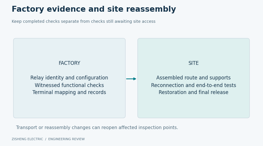
Shipping can change the configuration that was inspected at the factory. List the components left installed, removed, separately packed or temporarily secured. Match identification marks to packing records and reassembly drawings. The site team needs to know which factory observations remain applicable and which must be repeated after the final mechanical arrangement is restored.
The device instructions should govern transport locking, handling and restoration to the operating configuration. Record responsibility for those actions in the delivery plan. A general packing statement such as “accessories supplied loose” is insufficient when several similar parts, terminal covers or pipe sections are involved. Provide enough traceable detail for the receiving team to identify the intended assembly without improvising.
Shipping release and site energization are separate approval stages.
The site acceptance plan should name the checks required after assembly and filling, and identify the personnel authorized to perform them. Link each site activity to the factory record it supplements. Where shipping involved disconnection, the site report should show the final as-installed configuration and the completion of the required interface checks.
Keep commissioning authorization separate from shipping authorization. A transformer may be acceptable for shipment while a site protection test remains an explicit prerequisite to energization. Conversely, a clean shipping dossier cannot close a new installation discrepancy. The project release register should distinguish these gates so that progress reporting does not accidentally convert an outstanding technical action into an accepted condition.
Organize the final file around equipment identity, mechanical arrangement, electrical interfaces, test evidence and outstanding actions. Include approved drawings, the applicable manufacturer's manual, inspection photographs, test records, shipping configuration and resolved nonconformities. Use consistent equipment tags and revision references. The reader should be able to trace each conclusion to a specific record without searching an unrelated certificate collection.
For procurement, request these deliverables when discussing the oil immersed transformer package. Confirm that the selected design actually uses the protection arrangement being specified. An accessory requirement should follow the transformer design and project duty rather than being copied indiscriminately across all liquid-filled equipment.
For a substation transformer package, identify the boundaries between the transformer supplier, protection panel supplier and EPC commissioning contractor. The final signal destination may be delivered by a different party from the local device. The interface register should therefore remain active until the project-defined receiving checks are complete.
Retain a concise revision history when drawings or test forms change during manufacture. Identify which earlier results remain valid and which activities were repeated because the change affected their basis. This prevents a dossier assembled from individually correct documents from presenting an inconsistent overall configuration. The final index should state the accepted revision of each key interface document.
During the owner handover meeting, walk through one alarm path and one trip path using the actual document references. This is a document traceability exercise, not an additional live test. If the team cannot follow either path across supplier boundaries, assign the missing reference before closing the documentation item.
Does every inspection and test refer to the delivered relay and transformer?
Are the mechanical arrangement and applicable instructions clearly identified?
Can alarm and trip paths be traced independently through the drawings?
Does each test record describe its actual boundary and limitations?
Are transport changes linked to controlled site restoration activities?
Are outstanding actions assigned to named owners and release stages?
Zisheng Electric can discuss the equipment drawings, accessory schedule and documentation required for a project-specific review through its customization service. Bringing those requirements into the enquiry helps the buyer define the expected evidence before inspection dates are fixed. The resulting transformer Buchholz relay interface review should support a clear, traceable engineering decision at each delivery stage.