Please Choose Your Language
Views: 0 Author: Zisheng Electric Technical Engineer Publish Time: 2026-09-01 Origin: Site
When an EPC contractor witnesses a transformer FAT, the winding-resistance results often appear straightforward: connect the instrument, wait for a stable value and enter the number in the report. In practice, this is one of the easiest routine tests to misread. A value that looks slightly different between phases may be correct because of conductor length and connection geometry. A neat three-phase balance can still hide an unstable tap-changer contact if the test sequence was poorly controlled.
At Zisheng Electric, we treat the transformer winding resistance test as a design-verification and assembly-quality check, not a box to tick. The measurement should confirm conductor continuity, terminal connections, tap progression and contact integrity. It also provides the reference data needed for load-loss calculations and future site diagnostics.
DC resistance is measured across each accessible winding circuit. The result reflects the conductor material and cross-section, mean turn length, number of turns, lead length, joints, bushings and the selected tap position. It is therefore linked to both electromagnetic design and workshop assembly.
A credible result answers four questions. Is the measured value consistent with the approved design? Do comparable phases follow the expected pattern? Does resistance change logically across every tap? Is the value stable enough to be used in the FAT report and loss correction?
The test does not, by itself, prove that a transformer can withstand a short circuit or that every insulation interface is sound. Those risks require other routine, type or special tests. The resistance record is one part of the evidence chain: design calculation → conductor and joint inspection → winding assembly → final connection → routine FAT.
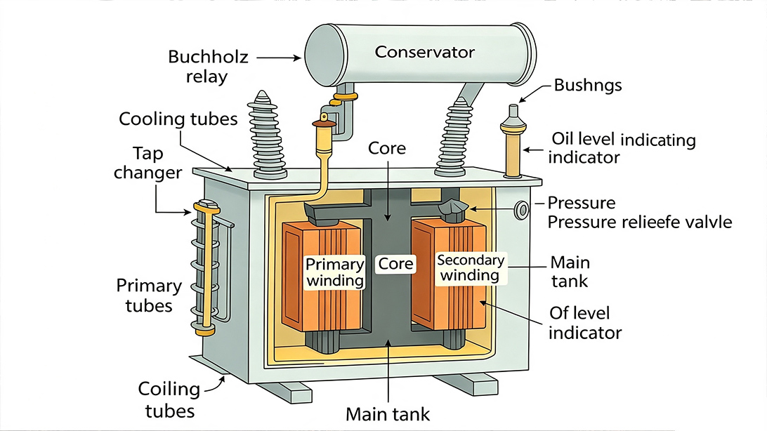
Internal winding and lead geometry determines the resistance pattern expected at the terminals.
Resistance values are meaningful only when the test conditions are traceable. The FAT team should identify the winding, connection, phase pair, tap position, conductor material, winding temperature and instrument range. If one item changes, the comparison basis changes as well.
Input | Why It Matters | Engineering Check |
|---|---|---|
Approved winding design | Defines turns, conductor section, mean turn length and predicted DC resistance | Compare measured values with the latest released calculation, not an obsolete tender drawing |
Vector connection | Terminal-to-terminal measurement may include one phase winding, two phase windings or a parallel path | State exactly which terminals were connected and how the design value was converted |
Tap position | Changing turns changes resistance; a tap sequence should form a logical trend | Record every tap and confirm the tap-changer indicator agrees with the actual electrical position |
Winding temperature | Copper and aluminium resistance changes with temperature | Use a representative winding temperature and record how it was obtained |
Test current and stability | Insufficient magnetization time produces drifting readings; excessive current can heat the winding | Use an approved procedure and save the stabilized value rather than the first displayed number |
Instrument and leads | Lead resistance and poor contact can dominate a low-resistance measurement | Use a four-terminal method, valid calibration and clean, tight terminal contacts |
Transformer windings can have very low resistance, especially on a high-current LV winding. A two-wire measurement includes the resistance of the test leads and contact points. A four-terminal, or Kelvin, connection separates the current leads from the potential leads so the instrument measures voltage at the transformer terminals rather than across the entire test circuit.
Clean terminal surfaces matter. Paint, oxide, loose clamps or a potential lead placed outside the current contact can create a false reading. During our FAT preparation, we normally check terminal identification, connection pressure and lead routing before energizing the resistance meter. This saves time later because unstable values are often caused by the test connection rather than the winding.
A transformer is an inductive device. After DC is applied, the current does not immediately reach steady state. Large windings and magnetic circuits may require patience. Recording a value while it is still drifting creates phase and tap differences that disappear when the test is repeated correctly.
The operator should monitor the rate of change, follow the instrument manufacturer’s method and define the stability criterion in the FAT procedure. The test current must be suitable for the winding and kept low enough to avoid changing the winding temperature during the measurement series. After testing, the core should be safely discharged and demagnetized in accordance with the equipment procedure before subsequent tests that could be affected by residual magnetism.
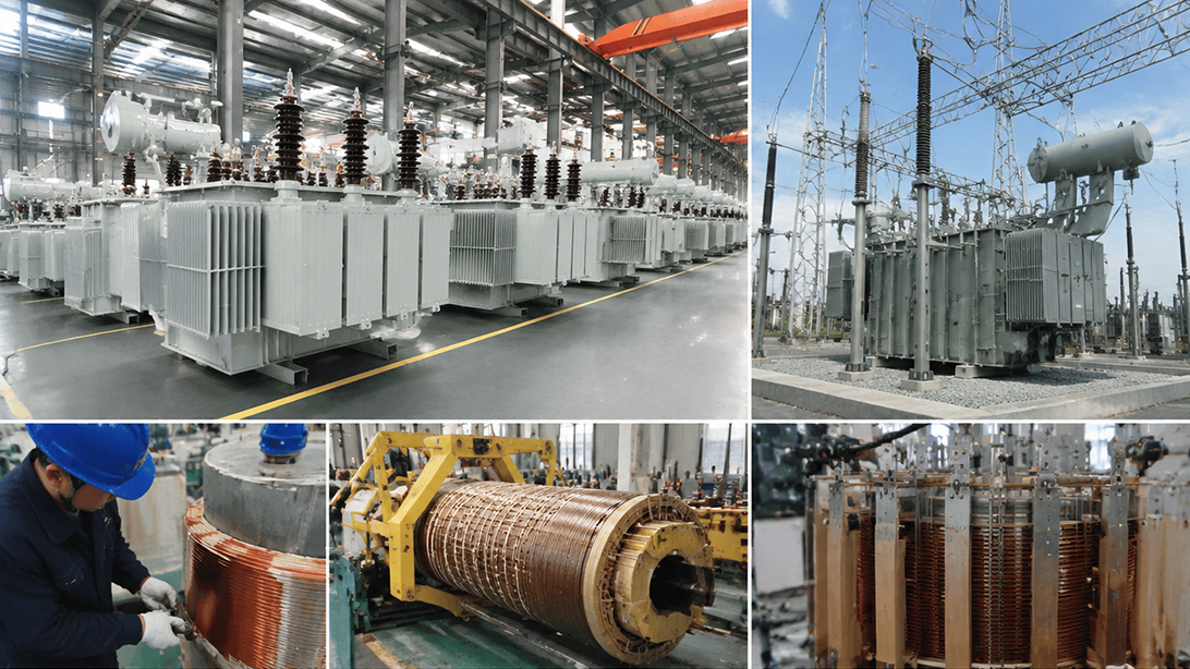
A controlled connection and stabilization sequence is essential for repeatable FAT resistance data.
Raw resistance readings taken at different temperatures cannot be compared directly. For a conductor whose reference constant is confirmed by the applicable test procedure, the corrected value can be expressed as:
R₂ = R₁ × (K + θ₂) / (K + θ₁)
R₁ is the measured resistance at temperature θ₁; R₂ is the resistance corrected to reference temperature θ₂; K is the material constant used by the governing standard or approved project procedure. Copper and aluminium use different constants. The FAT report should state the material, temperatures, constant and calculation basis rather than presenting a corrected value with no traceability.
Consider a copper winding measured at 24°C with a resistance of 1.250 Ω. Using K = 235 and correcting to 75°C gives approximately 1.496 Ω. That change is large enough to invalidate phase comparisons or loss calculations if temperature correction is omitted.
The harder question is the winding temperature itself. If the unit has been in a stable workshop for sufficient time, average oil temperature and ambient history may support a representative value. After another test has heated the transformer, one thermometer reading is rarely enough. The FAT sequence should therefore be planned so resistance measurement and temperature records are technically compatible.
Many specifications set a phase-deviation limit, but a universal percentage should not be applied without understanding the winding arrangement. Delta-connected windings, unequal external leads, internal parallel conductors and tap placement can produce designed differences. The correct acceptance basis is the approved calculation, project specification, IEC test requirements and the manufacturer’s documented tolerances.
Start with the design-predicted terminal resistance. Check whether the measured phase pattern matches the calculated pattern. Compare readings after correction to the same temperature. Then review repeatability and the progression through tap positions. A single isolated value deserves investigation even if the overall average is close.
On an off-circuit tap changer, resistance should normally change smoothly as turns are added or removed. An unexpected jump, reversal or unstable value may indicate a selector-position issue, a loose joint or a measurement made before stabilization. On an on-load tap changer, the test plan must recognize transition resistors, diverter mechanisms and the manufacturer’s approved measurement method. Do not force a simple off-circuit-tap interpretation onto a different switching design.
Observed Signature | Main Risk | What the Engineer Should Check |
|---|---|---|
One phase consistently high | Loose joint, incorrect conductor path or added lead resistance | Repeat Kelvin connections, compare design lead lengths, inspect terminal and internal joints |
Reading continues to drift | Insufficient stabilization, poor contact or changing temperature | Review current build-up, clamps, instrument range and winding thermal condition |
One tap breaks the expected trend | Tap selector position, contact or lead-connection problem | Operate through the sequence, verify mechanical indication and repeat the affected positions |
All values differ from calculation by a similar amount | Wrong temperature basis, conversion error or outdated design reference | Recheck material constant, terminal connection model, drawing revision and units |
Good FAT value but higher site value | Different temperature, bushing/contact condition or transport-related connection issue | Correct both datasets to one temperature and inspect site-installed links and terminals |
Measured winding resistance supports the I⊃2;R component used when correcting load loss to the reference temperature. If the resistance record is unreliable, the loss correction inherits that uncertainty. This is why the transformer winding resistance test should be reviewed together with the load-loss and impedance test, not filed as an unrelated sheet.
For engineers reviewing fault-current performance, our guide to transformer short-circuit impedance design and FAT verification explains how impedance affects both protection duty and voltage performance. The article on oil-immersed transformer manufacturing and FAT places resistance testing in the wider production sequence.
A useful witness checklist should be short enough to use beside the test bay and detailed enough to prevent ambiguous results.
Confirm the transformer serial number, winding ratings, connection and approved drawing revision.
Identify every measured terminal pair and tap position.
Verify instrument calibration status and four-terminal lead arrangement.
Record test current, raw resistance, stabilization evidence and winding temperature.
Correct results to the specified reference temperature using the agreed conductor constant.
Compare with design values, phase pattern and tap progression.
Investigate anomalies before the transformer is released; do not replace a failed point with an unexplained retest.
Discharge and demagnetize safely before moving to the next test.
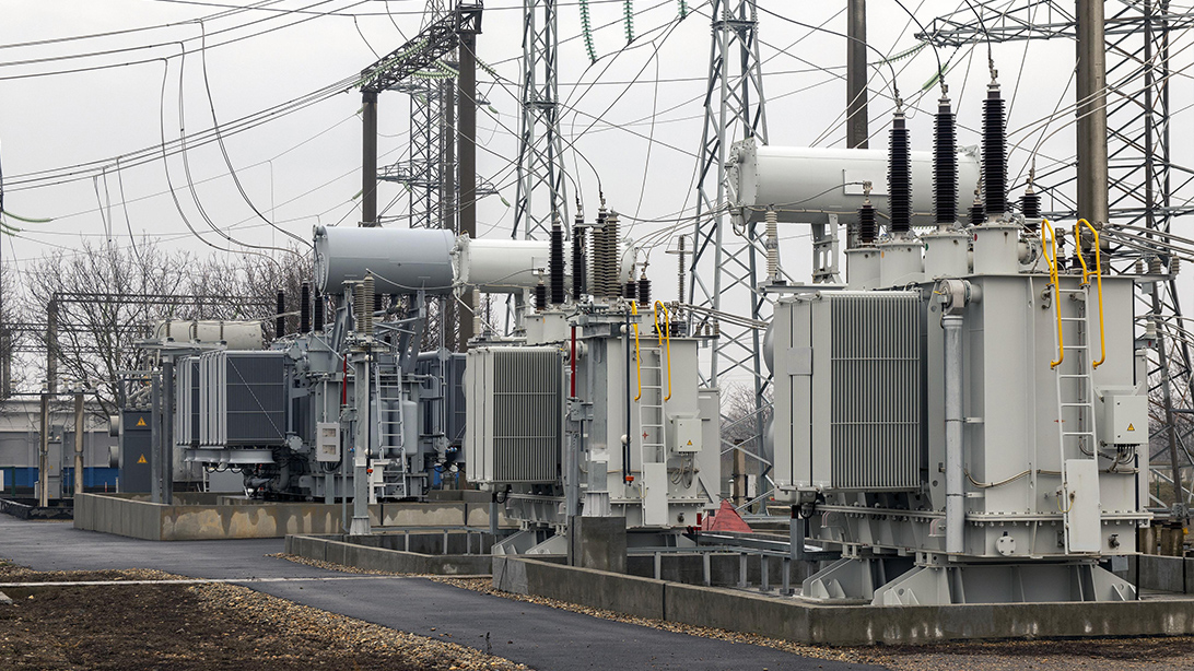
Terminal identification and tap position must remain traceable throughout the resistance test.
The resistance report becomes more valuable after delivery. Site teams can compare post-assembly or commissioning measurements with the FAT baseline, provided both are corrected to the same temperature and measured at identical taps and terminals. This can reveal a damaged transport connection, incorrectly installed removable link or deteriorating contact long before a thermal problem becomes visible.
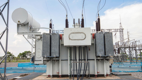
For packaged distribution projects, the same logic applies to an enclosed pad-mounted transformer. For utility and industrial substations, the test record should remain with the documentation for the specified oil-immersed power transformer and its maintenance history.
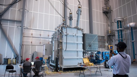
Site resistance measurements are most useful when the FAT baseline is complete and temperature-corrected.
A purchase specification sometimes asks only for “winding resistance measured” and leaves the acceptance method undefined. That wording is not enough for a witnessed FAT. The supplier and purchaser should agree on terminal pairs, all required taps, reference temperature, reporting precision and the comparison basis before the test date. Otherwise, the witness meeting can turn into a debate about calculations rather than an inspection of the transformer.
Another mistake is copying a phase-balance limit from a different transformer type. A three-limb distribution transformer, a unit with external LV bus links and a large power transformer with parallel winding paths do not necessarily produce the same terminal pattern. The design calculation should explain the expected asymmetry. Any purchaser limit should be applied to comparable quantities after temperature correction.
Finally, do not request repeated high-current measurements simply because the displayed value changes. Repetition without diagnosing stability can warm the winding and move the target. The better sequence is to verify the connection, monitor the trend, allow stabilization, document the raw data and investigate the physical cause of any anomaly. A clean FAT record is created by a controlled method, not by selecting the most convenient reading.
For a project-specific resistance procedure, send the transformer datasheet, winding connection, tap range, conductor material, project test specification, required reference temperature and FAT witness format. Zisheng Electric can align the routine test record with the approved design and the project’s acceptance workflow.
Zisheng Electric can provide technical matching based on project capacity, voltage level, environmental conditions and technical specifications. Our engineering team will review the requirements and respond to project inquiries within 24 hours.