Please Choose Your Language
Views: 0 Author: Zisheng Electric Technical Engineer Publish Time: 2026-09-04 Origin: Site
A transformer enquiry can contain the correct capacity and voltage ratio yet leave its insulation requirement unresolved. “Suitable for the system voltage” is not enough information to approve a winding design, select bushings or prepare a dielectric test schedule. For Zisheng Electric enquiries, transformer insulation level selection needs a terminal-by-terminal review before the technical offer becomes a manufacturing instruction.
The distinction is practical. Continuous operating voltage, short-duration overvoltage and an impulse do not impose the same stress. The line terminal and neutral terminal may not have the same insulation arrangement. An external air clearance does not describe insulation inside a winding. Procurement should connect these requirements without compressing them into one unexplained kV value.
Review the insulation requirement at each accessible terminal, not only the transformer voltage ratio.
List every winding and its accessible terminals. Identify the rated voltage, the highest voltage for equipment, the connection arrangement and the neutral treatment. Include a tertiary winding where supplied. Record whether a terminal is brought out, permanently connected internally or subject to a special operating arrangement. The drawing and the datasheet must describe the same configuration.
Rated winding voltage belongs to the transformer’s electrical rating. Highest voltage for equipment, commonly written Um, is a separate insulation-coordination parameter. Do not substitute one for the other. A familiar nominal network voltage is not sufficient authority to copy an insulation level from an unrelated project, especially when the purchaser has specific utility or installation requirements.
At Zisheng Electric, the useful design-review question is whether each insulation value can be traced to a named winding and terminal. A single line saying “HV insulation: confirmed” leaves too much open. Request an insulation schedule with units, applicable waveform or test category, and the document that establishes the requirement.
Input | Why it matters | Procurement check |
|---|---|---|
Rated voltage and Um for each winding | Operating rating and insulation class are different parameters | Record both explicitly and reconcile them with the approved system data. |
Line and neutral terminal arrangement | Terminal stresses and permitted insulation design may differ | Identify accessible neutrals and the specified earthing arrangement. |
Required withstand levels | Different voltage stresses require different verification | Separate impulse and AC requirements; identify peak or RMS units as applicable. |
Service environment | External insulation may need additional consideration | Confirm altitude, pollution exposure and installation geometry from project data. |
Dielectric test schedule | A generic factory test statement can omit an important requirement | Map each required test to the winding, terminal and acceptance document. |
Insulation coordination starts with the electrical system and its overvoltages, protective measures and operating conditions. The transformer manufacturer needs the resulting equipment requirements. The EPC electrical designer or system-study specialist should establish the system assumptions; the manufacturer should confirm that the offered transformer design and test scope satisfy the specified requirements.
IEC 60071-1:2019 addresses the selection of rated withstand voltages for insulation in three-phase AC systems with a highest voltage for equipment above 1 kV. Its role is broader than a transformer factory test sheet. This distinction helps keep system-level decisions and equipment verification properly connected. Standards reference: IEC 60071-1:2019, Insulation co-ordination — Definitions, principles and rules.
For an oil-immersed power transformer, ask the designer to provide the approved insulation-coordination requirements rather than asking the factory to infer them from the product title. A voltage-class label describes a product range, not a complete project-specific insulation schedule.
Where surge arresters are part of the protection scheme, their selection and placement belong in the coordination review. Do not assume that adding an arrester permits an arbitrary reduction in transformer withstand level. The protective characteristics, system earthing, connection arrangement and physical installation must support the proposed coordination.
Provide the manufacturer with the relevant study conclusions and interface drawings. If the arrester arrangement changes after design approval, ask whether the change affects the transformer requirement. A commercial substitution should not silently alter an engineering assumption on which the insulation design depends.
Lightning impulse withstand and AC withstand are not interchangeable quantities. They represent different applied stresses and verification methods. A larger-looking number is not automatically a stronger or equivalent requirement. Check the waveform, units, terminal designation and applicable test before comparing offers.
In particular, do not compare an impulse peak voltage directly with an AC RMS value. Label the columns clearly. If a quotation abbreviates a requirement, request its full meaning. Terms from different standards systems should be mapped explicitly rather than assumed equivalent because both are expressed in kilovolts.
IEC 60076-3 specifies transformer insulation requirements and corresponding tests with reference to individual windings and terminals, and includes recommendations for external air clearances. It provides a transformer-specific basis for the insulation schedule and dielectric test review. The project must state the applicable edition and amendments. Standards reference: IEC 60076-3:2013, Insulation levels, dielectric tests and external clearances in air; account for the applicable 2018 amendment.
Do not require every possible dielectric test simply because it appears in a standards catalogue. Applicability depends on the equipment and specified requirements. Conversely, do not accept “routine tests included” as a complete answer when the contract calls for additional dielectric verification. Resolve the test scope before the price and delivery programme are frozen.
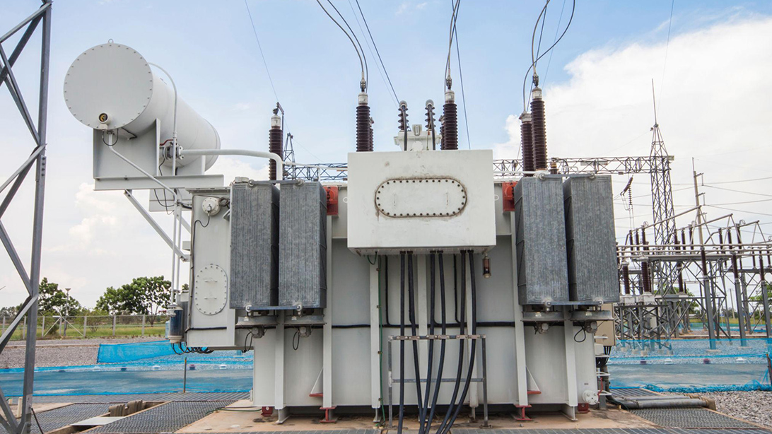
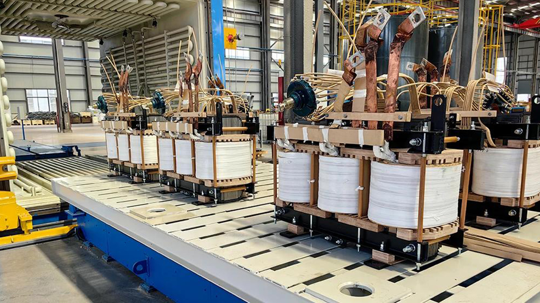
Winding insulation is designed as a system; external terminal ratings alone do not describe it.
A star-connected winding can have a neutral terminal with requirements different from those of its line terminals. The actual arrangement must follow the specified system and transformer design. Never assume that a neutral is at earth potential under every relevant condition simply because the single-line diagram contains an earth symbol.
Confirm whether the neutral is directly earthed, connected through an impedance, left isolated or subject to another defined arrangement. Ask about credible operating changes and the permitted configuration. If the project might change its neutral treatment later, that possibility belongs in the initial engineering discussion, not in an undocumented site modification.
Uniform and non-uniform insulation describe design arrangements that cannot be chosen from procurement shorthand alone. Where a reduced neutral insulation level is proposed, request confirmation that it is consistent with the system requirements and the applicable transformer standard. Identify the neutral terminal rating and test requirement explicitly on the approved schedule.
Changing an earthing resistor, connection arrangement or operating philosophy may alter the assumptions behind the insulation selection. The consequence is not necessarily that the transformer must be replaced; the consequence is that a qualified review is needed. Obtain written disposition before treating the revised arrangement as acceptable.
For a smaller distribution transformer for a substation, the same principle applies. Capacity does not remove the need to identify the winding connection and neutral arrangement. An apparently simple distribution package still has an insulation interface with the connected network.
Air clearance is a distance through air. Creepage is a path along an insulating surface. Internal insulation concerns the dielectric system within the transformer. These address different physical paths and should not be collapsed into one “insulation distance” on a supplier comparison sheet.
A longer bushing does not automatically prove a higher internal winding withstand capability. A suitable winding test result does not prove that a cramped cable termination arrangement has adequate external clearance. Review the complete installed geometry, including connected conductors, cable boxes, adjacent equipment and earthed metalwork.
Altitude and pollution exposure need project-specific attention. Do not use a country name as a substitute for site data, and do not apply a universal percentage adjustment without the applicable design basis. Ask the responsible designer to define the environmental requirements and the manufacturer to confirm the corresponding external-insulation arrangement.
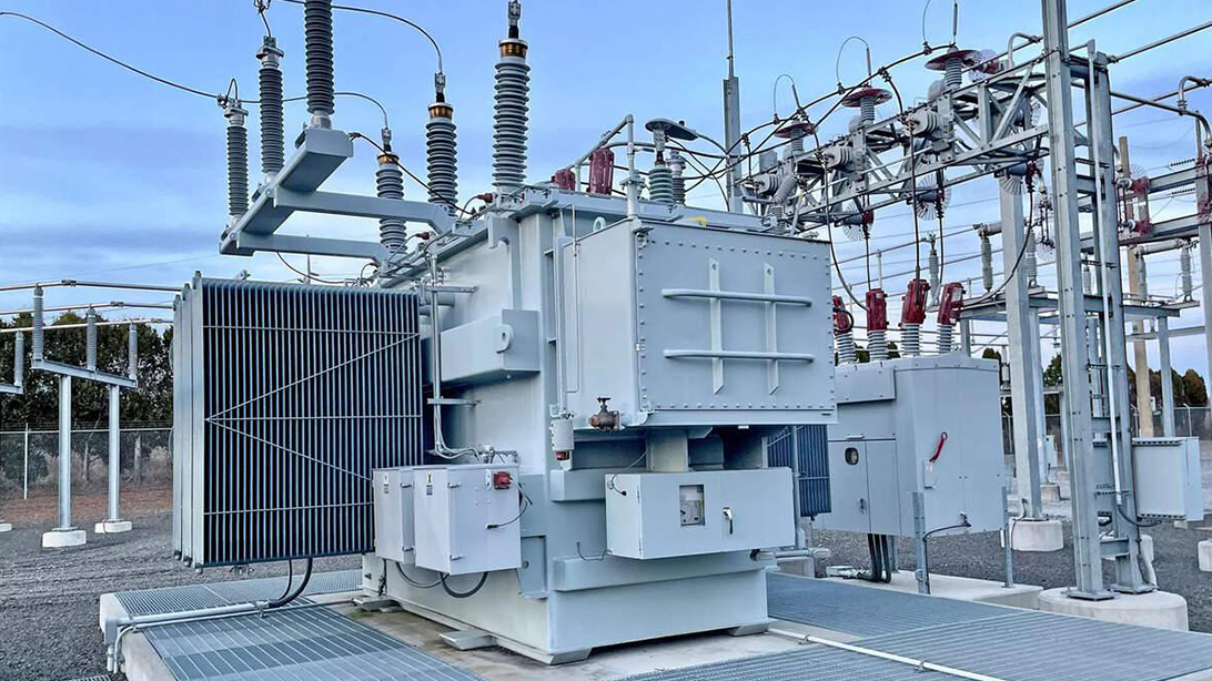
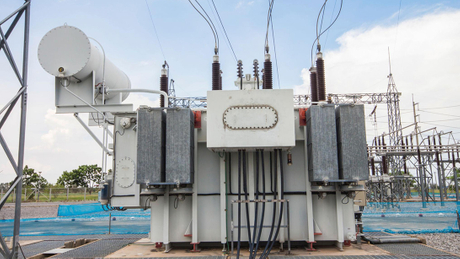
Installed conductor geometry and surrounding equipment are part of the external-insulation review.
Coordinate these checks with the broader industrial transformer design review. Capacity, cooling and installation conditions remain important, but none replaces an explicit insulation schedule.
The factory test plan should identify the transformer, winding and terminal to which each dielectric requirement applies. Include the agreed test category, level, procedure reference, witness requirement and acceptance basis. If partial-discharge measurement is required, its conditions and acceptance criteria must be specified; do not insert a universal picocoulomb limit into every transformer enquiry.
Distinguish applied-voltage and induced-voltage tests by their agreed purpose and procedure. They do not stress every part of the insulation system in the same way. Impulse testing also has its own circuit, waveform and interpretation requirements. Testing personnel must use the applicable approved procedure; a procurement article is not an instruction for operating high-voltage test equipment.
The current IEC publication for impulse-test methods is IEC 60076-4:2026. Its official scope covers lightning and switching impulse tests, including test circuits, measurements and interpretation. Where a contract names an earlier edition, resolve the contractual requirement with the purchaser rather than silently replacing it. Standards reference: IEC 60076-4:2026, Lightning impulse and switching impulse tests.
Review item | Common error | Required clarification |
|---|---|---|
Withstand values | A peak impulse value is compared with an AC RMS value | Separate columns, units and test designations. |
Neutral insulation | Only line-terminal values appear in the datasheet | State the neutral arrangement and applicable insulation requirements. |
Test applicability | Every test is called routine, or an important test is omitted | Agree a winding-by-winding test matrix and witness scope. |
External connections | Factory bushing spacing is accepted without installed conductors | Review the final termination and adjacent-metalwork geometry. |
Design change | A new earthing or protection arrangement is treated as equivalent | Reopen the affected coordination assumptions and record approval. |
A useful report identifies the unit and records the conditions needed to interpret the result. Confirm that the tested configuration corresponds to the supplied equipment and that any deviations have been approved. The report should make it possible to connect the evidence back to the original insulation schedule without relying on a verbal explanation.
Check document revisions carefully. If the datasheet changes between design approval and FAT, the test schedule must be reconciled with it. A report can be technically well prepared and still refer to an obsolete requirement. Keep the approved requirement, method statement and test record together in the review package.
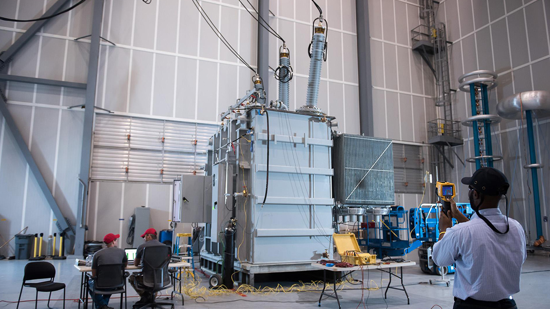
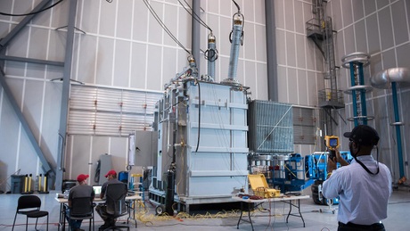
Dielectric verification needs a traceable procedure and report; the photograph does not establish a test result.
Other electrical tests remain valuable but answer different questions. A satisfactory no-load loss test does not establish impulse withstand. Likewise, a transformer ratio check is not a substitute for the specified dielectric verification. Keep the purpose of each test clear in the acceptance discussion.
An insulation change can affect more than a nameplate entry. Depending on the design, it may affect winding geometry, clearances, bushings, tank arrangement, test scope or delivery planning. Ask for an engineering impact review rather than assuming that a higher value is a harmless paperwork improvement.
The buyer should approve a coherent set of documents: system requirements, transformer datasheet, terminal arrangement and dielectric test schedule. Resolve discrepancies in writing. If two documents disagree, identify the governing requirement through the project’s approval process; do not let the workshop or site crew choose whichever value is most convenient.
For transformer insulation level selection, send Zisheng Electric the single-line diagram, winding ratings, Um values, neutral-earthing arrangement, insulation-coordination requirements and site conditions. Our team can provide technical matching for oil-immersed power transformers, distribution transformers and associated equipment against the project specification. Our engineering team will review the requirements and respond to project inquiries within 24 hours.