Please Choose Your Language
Views: 0 Author: Site Editor Publish Time: 2026-08-28 Origin: Site
When engineers review a transformer specification, attention usually goes first to winding temperature rise, impedance, insulation level, cooling method and load loss. At Zisheng Electric, however, one of the areas we check very early in the electromagnetic design is the transformer core.
There is a practical reason for this.
Copper loss changes with load. Core loss does not disappear when the factory stops production at night or when a distribution transformer is carrying only 20% load. As long as the transformer remains energized, the core continues to work.
That makes transformer core design closely related not only to efficiency, but also to operating temperature, noise, excitation current and long-term insulation condition.
For transformers operating in the Middle East and Africa, these details deserve more attention. High ambient temperatures, voltage fluctuation, long distribution feeders and different 50 Hz/60 Hz system requirements can reduce the design margin of a transformer that looks perfectly acceptable on paper.
A transformer core provides the magnetic path that links the primary and secondary windings. Every AC cycle requires the magnetic material to be magnetized in one direction and then reversed.
Energy is lost during this process.
In practical transformer engineering, core loss is mainly divided into hysteresis loss and eddy-current loss.
Hysteresis loss depends strongly on the magnetic properties of the electrical steel and the operating flux density. Eddy-current loss is generated by currents induced inside the steel itself. This is one reason transformer cores are constructed from thin insulated laminations rather than a solid steel block.
Manufacturers of grain-oriented electrical steel likewise identify thinner laminations, material grade and magnetic orientation as important factors in reducing transformer losses.
For a distribution transformer that remains energized throughout the year, even a relatively small difference in no-load loss accumulates continuously. This is why comparing transformer efficiency only at rated load can miss part of the real operating cost.
Most conventional power and distribution transformers use cold-rolled grain-oriented electrical steel, normally referred to as CRGO silicon steel.
But simply writing “CRGO core” in a technical specification tells an engineer very little.
Different steel grades have different specific losses, permeability characteristics, coating properties and saturation behaviour. Sheet thickness also varies.
Higher-performance electrical steel can reduce the energy required for magnetization. Thin laminations help restrict circulating eddy currents inside each sheet. Magnetic-domain-refined grades can reduce losses further under suitable operating conditions.
A lower-loss transformer core produces less internal heat during continuous energization, reducing the thermal burden on the oil, windings and cooling system.
A lower-loss transformer core produces less internal heat during continuous energization. The transformer cooling system therefore has less heat to remove before load losses are even considered.
In a mild climate this may simply improve efficiency. In a 45–50°C outdoor installation, that additional thermal margin becomes much more valuable.
Eddy-current loss increases when circulating currents are allowed to develop over larger conductive areas.
Transformer manufacturers address this by dividing the core into many thin sheets and electrically insulating one lamination from the next.
Sheet thickness therefore matters.
Electrical-steel research and manufacturer data show that reducing lamination thickness is an established method of lowering eddy-current loss. The relationship becomes particularly important as frequency and flux density increase.
There is another manufacturing issue engineers sometimes overlook: damaging the insulation coating during cutting, stacking or clamping.
If adjacent laminations are electrically bridged by heavy burrs, damaged coating or conductive contamination, localized circulating currents may develop. The drawing may still show a good core design, but the manufactured core no longer performs exactly as calculated.
That is why material selection and manufacturing quality cannot be separated.
One of the most important parameters in transformer core design is the operating transformer core flux density, because it directly affects no-load loss, excitation current and magnetic margin.A simplified transformer relationship can be written as:
B ≈ V / (4.44 × f × N × A)
where B is magnetic flux density, V is applied voltage, f is frequency, N is winding turns and A is effective core area.
This equation explains several practical design problems.
Increasing flux density can reduce the required core cross-section and make the transformer more compact. Push it too far, however, and core loss, excitation current and acoustic noise rise quickly as the material moves closer to saturation.
Using an unnecessarily low flux density is not automatically a good design either. The core becomes larger and heavier, material consumption increases, and winding dimensions may also be affected.
The engineering target is therefore not the lowest or highest possible value. It is an operating point that balances loss, size, cost, noise and magnetic margin for the actual project conditions.
This matters when transformers are supplied to different countries.
Most African power systems operate at 50 Hz, while project specifications in parts of the Middle East may require either 50 Hz or 60 Hz depending on the utility and application.The transformer must be calculated for the frequency stated in the project specification.
The key issue is the V/f ratio.
Running equipment designed around a 60 Hz magnetic condition on a 50 Hz supply at the same voltage increases flux density unless the design provides sufficient margin. That can increase excitation current, core loss, vibration and heating.
We therefore do not treat 50 Hz and 60 Hz as a nameplate detail added at the end of design. It belongs in the magnetic calculation from the beginning.
A transformer core cannot be built from one continuous piece of electrical steel. Individual laminations have to meet at the limb and yoke joints.
Poor joint design creates magnetic discontinuities.
The magnetic flux then has to cross larger effective gaps or deviate from the preferred rolling direction of the steel. Local flux concentration increases, which can raise excitation current, no-load loss and noise.
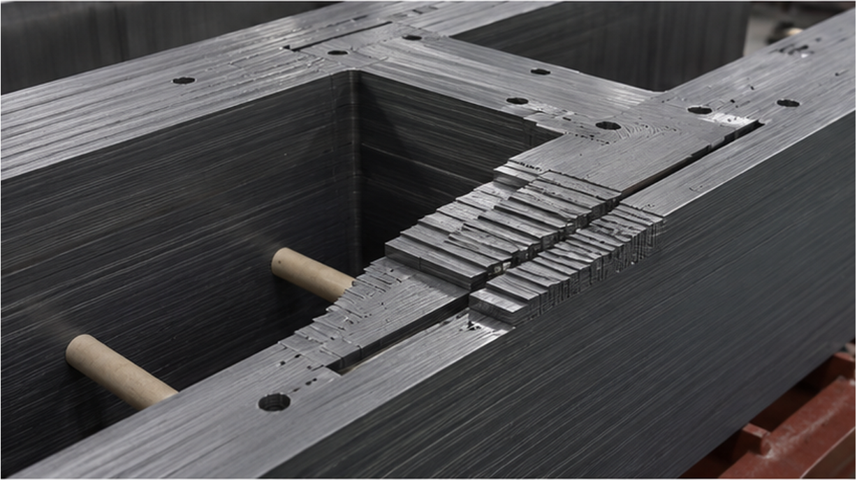
Modern cores commonly use fully mitered step-lap joints. Instead of concentrating the joint at one location, successive laminations overlap in steps.
The objective is smoother flux transfer through the joint region.
Cutting accuracy and stacking alignment become critical here. A good electromagnetic calculation cannot compensate for a badly stacked core with irregular gaps.
This is one reason we regard the transformer core stacking process as a controlled manufacturing operation rather than simple sheet assembly.
For a more detailed look at cutting, stacking and active-part manufacturing, see our IEC Transformer Manufacturing Process guide. IEC Transformer Manufacturing Process
At Zisheng Electric, we do not treat core performance as a material specification alone. During transformer core assembly, our engineers check lamination alignment, cutting burrs, step-lap joint consistency, insulation coating condition and clamping uniformity. Even high-grade CRGO steel can show higher no-load loss if the laminations are damaged or poorly stacked. These checks help keep the manufactured core close to the original electromagnetic design.
Once the core has been stacked, it needs enough mechanical support to remain stable during winding assembly, transportation and operation.
More clamping force is not necessarily better.
Electrical steel is sensitive to mechanical stress. Excessive local pressure, deformation or poor clamping arrangement can degrade magnetic performance. Insufficient clamping creates a different problem: laminations may vibrate more easily, increasing operating noise and mechanical movement.
The core clamping structure therefore has two jobs at the same time.
It has to hold the magnetic circuit mechanically stable without creating unnecessary stress in the electrical steel.
This is especially relevant for large transformers transported over long distances to Middle East or African project sites, where road conditions and handling may be very different from those inside the factory.
The transformer core normally requires a controlled grounding arrangement.
In many designs, the core is intentionally grounded at one point.
Multiple unintended grounding points can create closed conductive loops. Stray magnetic flux may then induce circulating currents through the core structure, clamps or grounding paths.
The result can be localized heating that is difficult to identify from external inspection.
During assembly and inspection, engineers therefore need to verify core-to-ground insulation and confirm that the grounding arrangement matches the approved design.
A core grounding problem does not necessarily appear immediately during commissioning. That is exactly what makes it a long-term reliability concern.
The electrical steel itself is usually not the component that determines transformer thermal life.
The more important link is this:
Higher core loss adds to the transformer’s total thermal load. If the cooling design and ambient margin are limited, the resulting increase in oil and winding temperatures can accelerate insulation aging.
IEC 60076-2 addresses temperature rise requirements and temperature-rise testing for liquid-immersed transformers, including winding hot-spot considerations.
This connection becomes particularly important in hot climates.
Suppose two transformers have identical capacity and load loss, but one has noticeably higher no-load loss. Under identical outdoor conditions, that additional core loss continuously becomes heat inside the transformer.
In a moderate climate the cooling system may absorb that difference comfortably.
At a Middle East industrial site with high summer ambient temperature, the available thermal margin is smaller. The cooling system has to deal with ambient heat, load loss and core loss at the same time.
Our article on Saudi Arabia transformer selection for 50°C environments discusses this thermal-margin issue in more detail. Saudi Arabia Transformer Selection Guide for 50°C Heat
Core Design Factor | Main Risk | Performance Impact | What Engineers Should Check |
Electrical steel grade | Higher specific loss | Higher no-load loss | Steel grade and guaranteed no-load loss |
Flux density | Operation near saturation | Higher excitation current and loss | Rated V/f and design flux density |
Step-lap joint | Local flux concentration | Higher loss and noise | Joint design and stacking quality |
Core grounding | Circulating current | Local overheating | Single-point grounding and insulation |
Lamination coating | Interlaminar current | Local loss and hot spots | Burr control and coating condition |
This is why engineers evaluating transformer quotations should not compare only capacity, impedance and price.
A technically stronger quotation should also define the core material, no-load loss guarantee, frequency, magnetic design basis and relevant factory tests.
The same transformer core can behave differently when project conditions change.
For high-temperature Middle East installations, lower internal losses help preserve cooling margin. Core loss cannot be considered separately from radiator design and winding temperature rise.
In African distribution networks, another condition appears frequently: long feeders and noticeable voltage variation.
An increase in applied voltage increases core flux density when frequency remains constant. A transformer designed with very little magnetic margin may therefore show a sharper increase in excitation current and no-load loss during sustained overvoltage.
Voltage waveform quality also matters. Harmonic voltage components introduce higher-frequency magnetic components, and core loss generally becomes more sensitive as frequency increases.
The correct response is not simply to “use better silicon steel.” Engineers need to review the complete operating condition: system voltage range, frequency, harmonic environment, ambient temperature and expected loading pattern.
Core design is primarily verified through both manufacturing control and electrical testing.
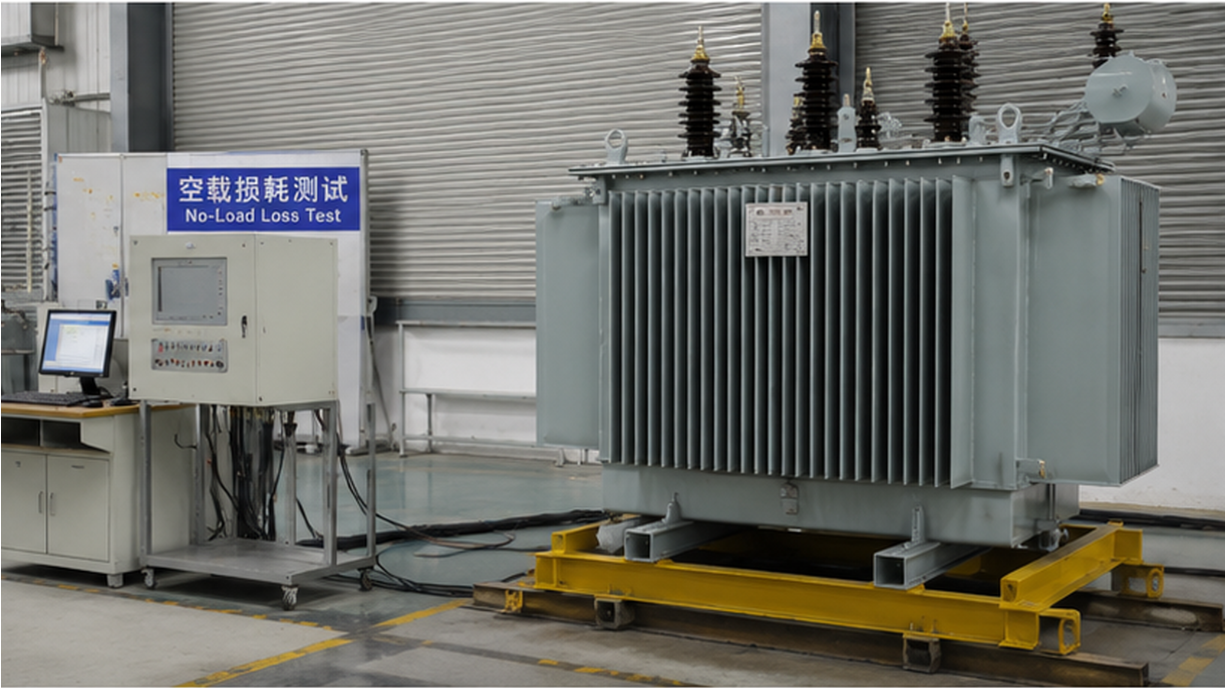
For the finished transformer, no-load loss and no-load current measurement are particularly important. These values provide a direct check on whether the manufactured magnetic circuit behaves close to the design calculation.
Unexpectedly high no-load current can indicate excessive flux density, core-joint problems, material differences or manufacturing deviations.
Unexpectedly high no-load loss deserves investigation rather than being accepted simply because the transformer can still energize normally.
Depending on project requirements, engineers may also review sound level, core insulation, excitation behaviour and related special tests.
IEC 60076-1 remains the general IEC standard for power transformers, covering ratings, general requirements and testing framework.
Transformer efficiency cannot be created by the nameplate.
Long before FAT, the performance of the transformer has already been influenced by electrical-steel selection, flux-density calculation, lamination cutting, step-lap design, stacking accuracy, clamping and grounding.
For engineers working on Middle East and African projects, we recommend looking at the transformer core together with temperature rise, cooling and actual network conditions rather than evaluating it as an isolated component.
Zisheng Electric supplies oil-immersed, dry-type, power, pad-mounted and pole-mounted transformers for EPC, utility, industrial and renewable-energy projects.