Please Choose Your Language
Views: 0 Author: Zisheng Electric Technical Engineer Publish Time: 2026-09-10 Origin: Site
Zisheng Electric reviews guaranteed transformer losses as part of design release because a loss figure is not only an efficiency number. It affects operating cost, temperature rise, cooling selection, tender evaluation and the evidence required at factory acceptance testing. A properly planned transformer load loss test gives the purchaser a defensible comparison between the guaranteed schedule and the completed unit. A poorly controlled test can produce a number that looks precise while hiding temperature, tap-position or measurement errors.
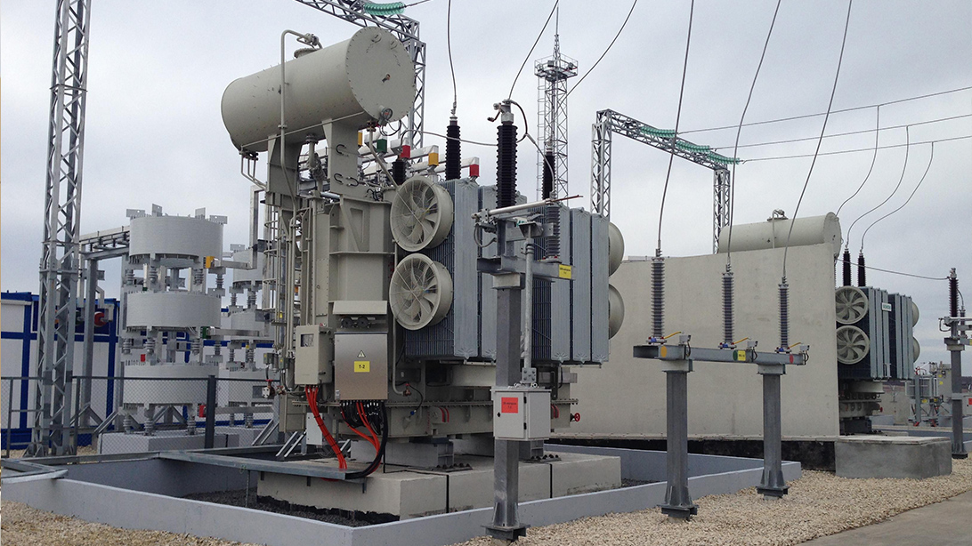
Oil-immersed transformer ready for electrical performance checks before project delivery.
The load loss test determines the power absorbed by a transformer when rated current flows through the windings under short-circuit test conditions. The measured result contains the winding resistance component and additional stray losses caused by leakage flux in conductors, structural parts, tank walls, clamps and other metallic components. It is therefore a check on more than copper quantity. It also reflects winding geometry, conductor transposition, joint quality and the control of leakage flux during design.
For an EPC contractor, the result affects three decisions. The first is lifetime energy cost. Load loss rises approximately with the square of current, so a unit that operates heavily loaded for long periods can accumulate a meaningful cost penalty. The second is thermal performance. The loss used for the temperature-rise test must be consistent with the agreed loss duty. The third is contractual compliance. If the tender includes guaranteed losses, the test report must allow the owner to compare the corrected measured value with the guarantee on the same basis.
A common procurement mistake is to compare one manufacturer’s measured value at the test temperature with another manufacturer’s guaranteed value at a reference temperature. Those are not equivalent figures. The review must confirm the reference temperature, principal tap, rated frequency, winding material and applicable tolerance before judging the result.
During the test, one winding is short-circuited and sufficient voltage is applied to the other winding to circulate the specified current. The applied voltage is only a fraction of rated voltage, but the current is at or near the contractual test value. Power analyzers measure voltage, current and input power. The input power, after instrument and connection considerations are addressed, represents the loss under the test condition.
The same test arrangement normally provides short-circuit impedance information. That does not mean the two values should be reviewed as one item. Impedance is a system-design parameter affecting fault current, voltage regulation and parallel operation. Load loss is an energy and thermal parameter. A unit can meet the impedance guarantee yet fail the load-loss guarantee, or the reverse.
At Zisheng Electric, we normally check the approved winding data, tap position, conductor material and expected resistance before energizing the test circuit. If the measured phase pattern is inconsistent with the design calculation, the right response is not to average the readings and continue. Connections, instruments and winding resistance data should be checked while the unit is still available for investigation.
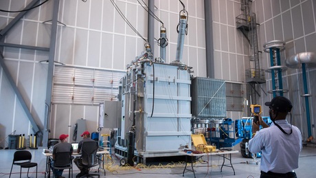
Test connections and instrument ranges should be verified before recording the load-loss result.
Winding resistance changes with temperature. The measured load loss must therefore be separated conceptually into its resistance and stray components before correction to the contractual reference temperature. For copper windings, resistance increases as temperature rises. The stray component follows a different temperature relationship. Applying one simple multiplier to the total measured watts can distort the corrected result.
The test report should state the measured winding temperature, how that temperature was established, the measured resistance used in the calculation and the reference temperature. If the transformer has just completed another electrical test or has been standing in a changing ambient, time must be allowed for a stable and representative resistance measurement. Guessing winding temperature from room temperature is not an acceptable substitute for recorded data.
Input | Why It Matters | Procurement Check |
|---|---|---|
Test current and duration | Loss varies with current; unstable readings reduce repeatability. | Confirm the recorded current for each phase and the agreed correction to rated current. |
Tap position | Resistance and leakage field distribution change across taps. | Identify the tested tap and any additional taps required by the specification. |
Winding temperature | Directly affects the resistance component of load loss. | Require measured resistance, temperature method and timestamp. |
Reference temperature | Creates the common basis for guarantee comparison. | Check the contract, conductor material and calculation formula. |
Instrument range and accuracy | Short-circuit tests can have a low power factor, increasing watt measurement sensitivity. | Review analyzer class, CT/VT ratios and calibration validity. |
Guaranteed load loss | Defines the acceptance benchmark and possible commercial consequences. | Compare corrected test value with the signed technical schedule, not a preliminary quotation. |
The resistance component is derived from measured winding resistance and current. Phase resistance consistency deserves attention because an abnormal difference may indicate a poor joint, incorrect connection, tap-changer contact issue or a temperature imbalance. Small differences can be expected from winding arrangement and lead length, but the engineering explanation should be visible in the records rather than assumed.
Stray load loss is the remainder after the resistance component is deducted from total measured load loss. It is influenced by leakage flux passing through windings and metallic structures. Higher-than-expected stray loss can point to conductor eddy effects, inadequate transposition, magnetic shielding issues or local structural heating risk. It should not be dismissed simply because the total result remains inside a broad tolerance.
This distinction is particularly useful when comparing the test result with the design calculation. If DC resistance agrees closely but the total load loss is high, the review should focus on stray effects and measurement quality. If the resistance component is high, conductor dimensions, mean turn length, joints and actual winding temperature become the first checks.
The voltage required to circulate rated current is relatively low, while reactive power in the test circuit can be high. The power factor can therefore be low. Under these conditions, small phase-angle errors in instrument transformers or transducers can produce a noticeable error in measured watts. An analyzer with adequate power accuracy for the expected power factor is more important than a display with many digits.
Test leads should be arranged consistently and kept clear of strong leakage fields where practical. Current transformers and voltage transformers must operate within their appropriate ranges. Ratio settings, polarity and channel assignments should be independently checked before the recorded run. A stable three-phase result is preferable; when single-phase methods are used, the report should clearly describe the sequence and calculation.
The official IEC description identifies IEC 60076-1 as the general standard for power transformers, including general requirements relevant to transformer testing and specification. The project specification remains the contractual document, so the test plan should state the applicable edition and any purchaser-specific requirements. See the official IEC 60076-1 publication page for the standard’s scope.
The signed data sheet should be on the test floor. Comparing against a value copied from an early quotation is risky because the final design may have changed after voltage ratio, impedance, tap range or accessory requirements were frozen. The guarantee basis must also be clear: individual load loss, total losses, capitalization formula, capitalization currency and any applicable tolerance.
Energy-cost evaluation should use the owner’s expected load profile rather than rated load alone. For a transformer carrying a fraction of rated load, the load-loss contribution follows the square of that load factor. A plant with a high continuous base load will value low load loss differently from a standby or seasonally loaded transformer. The commercial evaluation should therefore distinguish purchase price from evaluated lifetime cost.
Loss comparison also needs to stay consistent with the selected voltage level and network duty. The engineering trade-offs are discussed further in our guide to 13.8 kV versus 34.5 kV transformer selection. For equipment options, review the oil-immersed transformer range and the 132 kV–138 kV power transformer configuration.
Design data, approved drawings and the guaranteed loss schedule should be available during FAT review.
Review Point | Main Risk | What the Witness Should Confirm |
|---|---|---|
Nameplate and test identity | Results assigned to the wrong unit or rating. | Serial number, rating, vector group, frequency and tap position match the approved documents. |
Short-circuit connection | Incorrect winding shorted or poor temporary connection. | Connection diagram, conductor size, joint condition and grounding are suitable. |
Instrument setup | Ratio, polarity or range error. | Calibration dates, channel mapping, CT/VT ratios and analyzer configuration are recorded. |
Raw readings | Only corrected values are reported, preventing independent review. | Phase voltage, current, watts, frequency and temperature are retained. |
Correction calculation | Wrong conductor constant or stray-loss relationship. | Formula, winding material, reference temperature and intermediate values are shown. |
Guarantee comparison | Acceptance against an obsolete data sheet. | The final approved loss schedule and contractual tolerance are identified. |
A high result should trigger a structured review. Start with test current, tap position, winding resistance, temperature and instrument configuration. Confirm that temporary short-circuit links are tight and that measured phase values are physically consistent. If the result remains high after repeatable measurements, compare resistance loss and stray loss separately with design values.
Repeating the test without changing or documenting anything does not create better evidence. The repeat should have a stated reason: corrected instrument range, stabilized winding temperature, repaired connection or verified analyzer setup. Both the original and repeat data should remain traceable in the FAT record when they form part of the investigation.
An unexpectedly low value also deserves attention. It can result from current below the intended value, incorrect scaling, missing phase channels or a calculation error. Acceptance should be based on credible measurement, not only on whether the number falls below the guarantee.
Loss performance, thermal design and operating temperature must be reviewed as one engineering chain.
The final package should contain the approved test procedure, instrument list and calibration references, raw measurement sheets, resistance records, temperature data, correction calculations, final load loss and impedance results, guarantee comparison and signed witness page where applicable. If a deviation was investigated, the resolution should be included rather than left in informal correspondence.
The load-loss report also supports later thermal and operational review. The relationship between losses and heat removal is covered in our transformer temperature-rise FAT guide. Keeping both reports on the same design and reference basis prevents a common handover problem: one document uses guaranteed losses while another silently uses measured losses.
A reliable transformer load loss test starts with a frozen technical schedule and ends with traceable calculations, not a single watt figure. Zisheng Electric can support oil-immersed distribution transformers and power transformers with design review, manufacturing records and FAT documentation matched to the project specification.
Send the transformer data sheet, guaranteed loss schedule, voltage ratio, tap range, impedance requirement, loading profile and FAT specification. Zisheng Electric can provide technical matching based on project capacity, voltage level, environmental conditions and technical specifications. Our engineering team will review the requirements and provide an initial response to project inquiries within 24 hours.