Please Choose Your Language
Zisheng Electric approaches 13.8kV vs 34.5kV transformer selection as a system decision rather than a nameplate comparison. The selected distribution voltage affects current, cable sizing, insulation class, switchgear, protection, substation footprint, losses and future expansion. The correct answer must begin with the utility point of connection, the approved single-line diagram and a verified load-flow study.
This guide gives EPC teams and industrial buyers a practical comparison framework. It does not assume that either voltage is universally better. Project engineers should confirm local utility rules, maximum system voltage, grounding method, insulation coordination, short-circuit duty, environmental conditions and equipment availability before issuing the transformer specification.
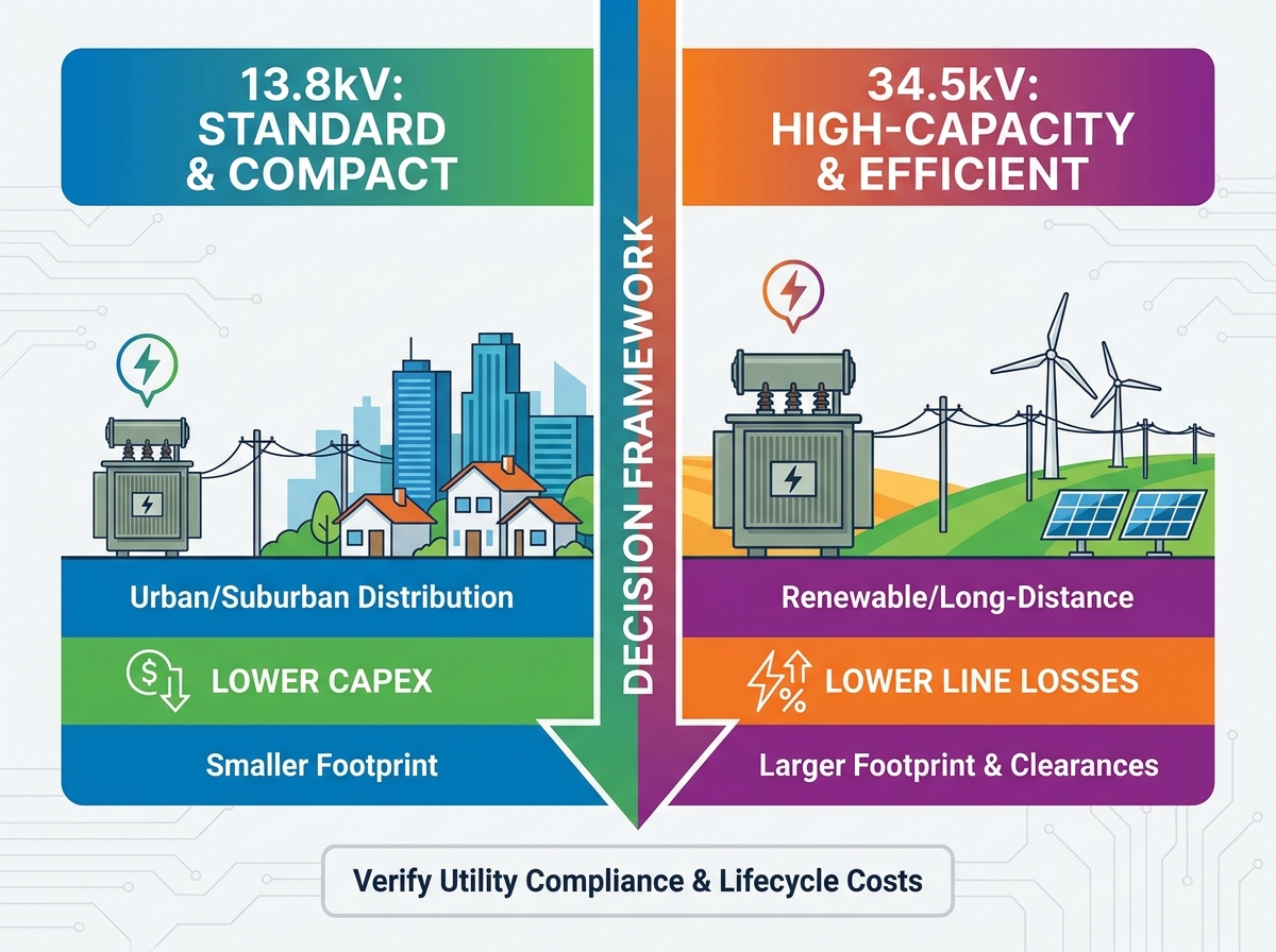
13.8kV systems offer broader standardized component availability, lower upfront CAPEX, and smaller equipment footprints for urban/suburban distribution.
34.5kV systems minimize line losses over long distances, making them critical for solar/wind farms and heavy industrial operations.
Integrating 34.5kV equipment requires specialized secondary risk mitigation, particularly regarding ungrounded wye configurations and ferroresonance.
Regional grid standards (e.g., ISO guidelines) dictate baseline compliance; procurement must align with local utility mandates before finalizing specifications.
Voltage selection is rarely a blank slate. You almost always face constraints from existing utility tie-ins and regional grid standards. Your project might demand high-efficiency power transmission, but local infrastructure ultimately dictates your baseline options. Engineers must first address these external business and regulatory realities before finalizing any internal site plans.
Utility practice differs by network and project. A nominal 13.8kV or 34.5kV designation does not by itself define the equipment class. The purchaser must state the highest voltage for equipment, system grounding, basic insulation level or lightning impulse withstand level, power-frequency withstand requirements and any utility-specific clearances. IEC 60076-1 provides general transformer requirements, while the approved project specification and utility documents govern the final design.
Verify your local interconnect agreements before advancing technical evaluations. We recommend opening a dialogue with your local utility provider immediately. Request their latest interconnect guidelines. Confirming the utility interconnection voltage at the project boundary saves thousands of dollars in wasted engineering hours. Only after securing utility approval should you move forward comparing specific transformer topologies.
The 13.8kV voltage class remains the workhorse of modern power distribution. Commercial distribution networks, residential step-down applications, and dense urban infrastructure heavily rely on this standard. Cities grew around 15kV class equipment. Because of this historical dominance, manufacturers optimized their production lines for these specific units.
When evaluating 13.8kV systems, you must consider several key dimensions:
CAPEX & Lead Times: Standardized manufacturing generally yields shorter lead times. You will spend less on procurement. Suppliers often stock components for these units, reducing project wait times.
Footprint & Clearance: Padmount and pole-mounted spatial requirements are highly favorable. The minimum dielectric clearances for 13.8kV are much smaller compared to higher voltage alternatives. You can fit these units into tight urban alleys, small industrial pads, or crowded utility poles.
Component Availability: Standard fuses, arresters, and switchgear for 15kV class systems are readily available from multiple vendors.
However, 13.8kV systems have distinct limitations. You face significant line loss inefficiencies if forced to distribute power over long distances without stepping up the voltage. Lower voltage means higher current for the same power delivery. Higher current exponentially increases resistive losses in your cables. When sourcing Single Phase Transformers for sprawling sites, these losses often become unacceptable. You must balance the low upfront cost against these inherent distribution limits.
As energy demands scale, 34.5kV systems provide necessary electrical muscle. Utility-scale solar and wind collection systems rely almost exclusively on this voltage class. Rural distribution networks covering vast geographies also utilize it heavily. Energy-intensive industrial facilities require 34.5kV to effectively distribute massive power loads across their campuses.
The primary advantage here is efficiency at scale. Pushing power at 34.5kV drastically reduces I⊃2;R (line) losses. Because current is lower at a higher voltage, the cables generate less heat and waste less energy. When moving megawatts across a sprawling 500-acre solar farm, this efficiency is non-negotiable. Standard 13.8kV distribution would require excessively thick, expensive copper cabling to achieve similar performance.
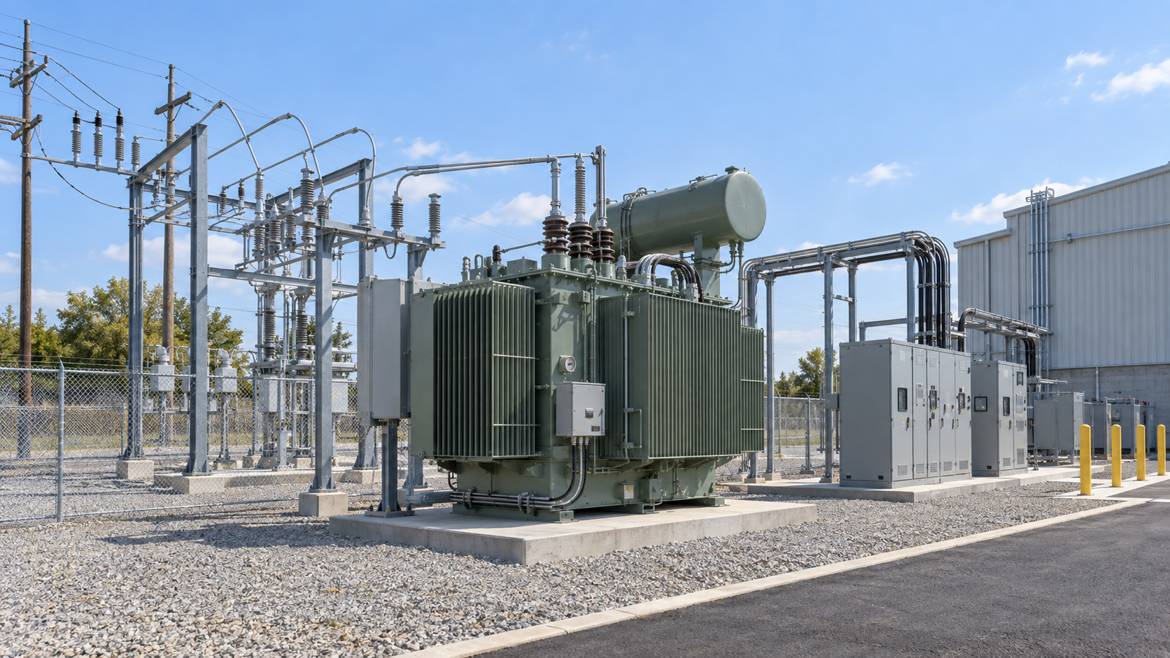
These efficiency gains demand significant infrastructure adjustments. The equipment physically scales up. You will need larger bushings to handle the increased voltage stress. The internal and external dielectric clearances increase substantially. You must reinforce structural supports to handle heavier core steel and higher oil volumes. The footprint grows, demanding larger concrete pads and wider maintenance perimeters.
Implementation realities also include higher operational expenditures. Specialized maintenance becomes a strict requirement. Your technicians need specialized training to handle 35kV class switchgear and protection systems. Additionally, you will face longer procurement cycles for non-standard configurations. Sourcing high-capacity Single Phase Transformers at this voltage often involves custom winding designs, meaning you must order well in advance of your deployment date.
Deploying 34.5kV equipment introduces complex secondary risks. You must identify and address specific engineering vulnerabilities early in the design phase. One major concern involves overvoltage risks in ungrounded wye secondary configurations during line faults. If a single line-to-ground fault occurs on the primary side, the ungrounded wye configuration can cause the unfaulted phases to experience massive overvoltages. This event can catastrophically degrade insulation.
To safely operate these systems, you need rigorous protection strategies. Proper grounding practices are mandatory. Engineers frequently employ sophisticated relay protection schemes to rapidly detect and clear asymmetrical faults before insulation failure occurs. You cannot cut corners on these safety investments.
Furthermore, ferroresonance poses a significant threat in lightly loaded 34.5kV systems. This phenomenon occurs when the capacitance of underground cables interacts with the nonlinear inductance of the transformer core. It generates highly distorted, dangerous overvoltages. To mitigate ferroresonance, you must enforce specific switching procedures. Utilities often mandate three-phase gang-operated switches rather than operating single-phase cutouts independently.
Weighing the performance benefits of 34.5kV against these safety requirements requires clear, evidence-based judgment. The efficiency gains over long distances are spectacular. However, you must dedicate engineering resources to properly protect the circuit. A poorly protected 34.5kV system is a liability. A properly engineered one guarantees long-term stability for heavy industrial and renewable applications.
Selecting the right voltage requires a logical, step-by-step framework. You must evaluate upfront capital expenditures against long-term operational efficiency. The 13.8kV option usually wins on initial equipment price, cabling costs, and pad size. Conversely, 34.5kV systems demand heavier cabling insulation and larger enclosures but recover value through vastly reduced operational line losses.
Follow this strict shortlisting logic to guide your procurement:
Step 1: Confirm utility interconnection voltage. Never specify equipment before securing an official interconnect agreement from the local utility provider.
Step 2: Calculate distance from generation to load. Evaluate the loss penalties. If your cable runs exceed standard local distribution lengths, calculate the I⊃2;R losses for both voltage classes.
Step 3: Assess footprint constraints. Measure site accessibility. Ensure your concrete pads and property lines accommodate the larger clearances mandated for 35kV class equipment.
Voltage Class Comparison Chart
Evaluation Criteria | 13.8kV Distribution | 34.5kV Distribution |
|---|---|---|
Primary Application | Urban, commercial, light industrial | Utility solar/wind, heavy industrial, rural |
Standardized Availability | High (shorter lead times) | Moderate to Low (longer lead times) |
Spatial Footprint | Compact (smaller phase clearances) | Large (extended dielectric clearances) |
Line Loss Efficiency | Lower efficiency over long distances | High efficiency over extended runs |
Secondary Risks | Standard protection schemes suffice | High risk of ferroresonance; demands complex relays |
Your actionable next step is to commission an engineering review. Run comprehensive load flow studies and fault analyses before initiating any Request for Quote (RFQ). Data-driven load studies reveal exactly how much voltage drop you will experience, guiding you to the most efficient equipment choice.
The choice between 13.8kV and 34.5kV shapes the physical and electrical foundation of your project. 13.8kV remains the cost-effective, highly standardized solution for localized, densely populated distribution grids. In contrast, 34.5kV serves as an absolute operational necessity for bridging long distances and supporting heavy renewable energy collection.
We advise buyers to prioritize utility compliance and long-term operational efficiency over initial equipment price tags. An undersized voltage class will choke your power delivery, while a mismatched system will fail utility interconnection standards. Base your decisions on hard data, load flow studies, and strict safety requirements.
For a project-specific review, send Zisheng Electric the single-line diagram, utility voltage, maximum system voltage, transformer kVA or MVA, load list, feeder lengths, short-circuit level, grounding method, insulation requirements, tap range, loss capitalization criteria and site conditions. Our engineering team will review the requirements and respond to project inquiries within 24 hours.
A: No. Doing so causes absolute dielectric failure. The insulation inside a 13.8kV unit cannot withstand the severe electrical stress of a 34.5kV grid, leading to immediate short circuits and catastrophic explosions. If you anticipate a future utility upgrade from 13.8kV to 34.5kV, you must specify and install dual-voltage transformers designed to handle both ratings safely.
A: These units require more specialized engineering. Manufacturers must utilize larger core steel and design custom winding configurations to handle higher voltage stresses. Additionally, 34.5kV equipment undergoes much more stringent factory acceptance testing protocols, including prolonged impulse and partial discharge tests. This rigorous process naturally extends manufacturing timelines.
A: A 34.5kV unit is significantly larger, often requiring 30% to 50% more physical footprint than a 13.8kV unit of the same kVA rating. This size increase directly results from mandatory phase clearance requirements. Higher voltages require greater distances between live parts and the grounded tank to prevent arcing, necessitating larger enclosures and bigger concrete pads.
A: Higher voltages demand stricter maintenance intervals. For 34.5kV units, you must increase oil testing frequency to detect dissolved gases early. Bushing inspections become hyper-critical, as any surface contamination can cause flashovers at 35kV. You also face stricter vegetation management rules to maintain safe clearance zones around the larger high-voltage infrastructure.