Please Choose Your Language
Views: 0 Author: Zisheng Electric Technical Engineer Publish Time: 2026-09-02 Origin: Zisheng Electric
A low loss figure is useful only when the conditions behind it are clear. For an enquiry to Zisheng Electric, a guaranteed value in watts should arrive with the voltage, frequency, tapping and acceptance basis that make that number meaningful. At FAT, a transformer no-load loss test should establish more than whether a display is below a limit. It should produce a result the purchaser can trace, compare and defend after the equipment leaves the factory.
The engineering chain is straightforward: the test supply establishes magnetic flux; the core responds to that excitation; the measurement system records active power and current; the inspection team decides whether the evidence meets the agreed specification. A weakness anywhere in that chain can make a sound transformer look defective, or allow a questionable result to pass without proper examination.
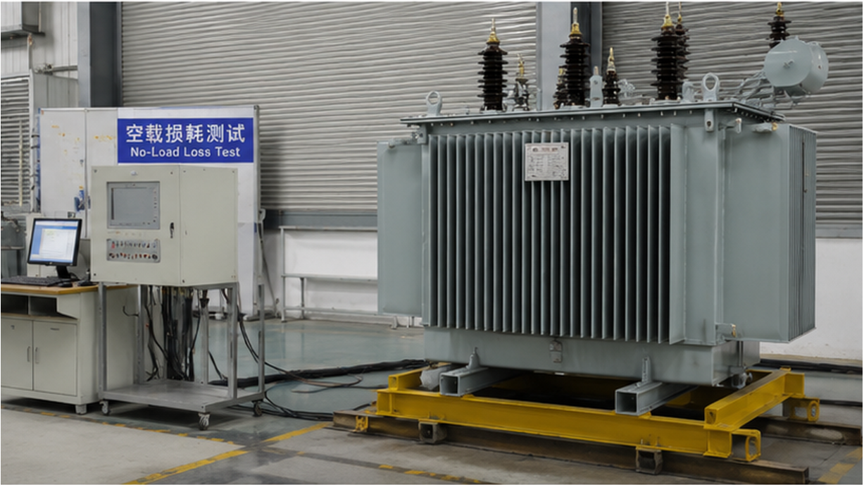
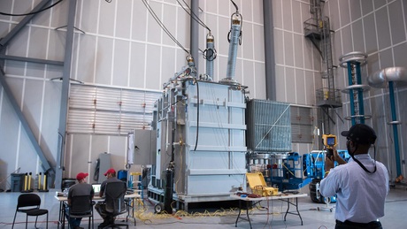
A no-load loss test arrangement combines the transformer, a controlled supply and a documented measurement chain.
With the other windings open-circuited, an energized winding draws current to establish alternating flux in the core. The supply provides the active power associated predominantly with core losses, together with smaller contributions that depend on the design and test arrangement. The measured no-load current also contains a substantial magnetizing component. Watts and amperes therefore describe different things.
Do not treat the product of voltage and current as the measured loss. Apparent power is not active power. In a three-phase test, the connection method, phase measurements and calculation of the reported total must be stated. A current percentage is equally incomplete unless its reference winding and rated-current basis are identified.
Does the transformer meet its guaranteed loss? Is the excitation-current pattern consistent with its design and previous evidence? Was the measurement valid? These questions are related, but none replaces the others. A satisfactory power reading does not certify insulation condition, short-circuit strength or temperature rise. Those require their own evidence within the agreed test programme.
Ask for the test procedure before the witness visit. It should identify the energized winding, terminal arrangement, tap position, rated frequency, target voltage and the state of every other winding. An accessible lower-voltage winding may simplify the supply arrangement, but it does not remove the need to control induced voltage on open terminals. Qualified test personnel must establish barriers, earthing arrangements and the approved switching procedure.
Magnetic flux depends strongly on voltage relative to frequency for a given winding. If frequency falls while voltage remains unchanged, the core can move toward a more heavily excited operating point. A reading taken under that condition cannot be compared casually with a guarantee based on a different frequency. The same caution applies when a tapping changes the effective turns in the energized winding.
If voltage increases by 2% and frequency falls by 1%, the voltage-to-frequency ratio becomes 1.02 divided by 0.99, approximately 1.030 times its previous value. That is roughly a 3% change in the excitation basis. It does not mean that no-load loss rises by exactly 3%. Core response is nonlinear, and the change in current can be more pronounced near saturation. Use the approved method, not a proportional guess, to handle deviations.
Test input | Main risk | Engineering check |
|---|---|---|
Applied voltage and frequency | A changed excitation point distorts comparison with the guarantee. | Record actual values during each accepted measurement, not only nominal settings. |
Energized winding and tap | Wrong reference voltage or turns makes the result misleading. | Match terminal markings, tap indication and the approved test connection diagram. |
Other winding connections | An unintended burden changes measured power and current. | Document open circuits, intentional connections and instrument burdens. |
Supply waveform | Distortion changes the relationship between meter readings and core excitation. | Retain the required waveform indicators and any approved correction calculation. |
Previous DC testing | Residual magnetism can complicate excitation-current interpretation. | Record the sequence and use the approved demagnetization procedure where required. |
Instrument ranges and calibration | Low-current or low-power-factor errors can dominate the reported loss. | Review the complete chain, selected ranges and applicable calibration evidence. |
Display resolution is not measurement accuracy. A meter can show several decimal places while its current transformer, voltage transformer, phase-angle response or selected range introduces a material error. The issue becomes particularly important when active power is small relative to apparent power. A small phase error can then have a disproportionate effect on the reported watts.
Review the measurement chain as a system. Identify sensors, ratios, polarity, burdens, connecting leads and the power analyzer configuration. Confirm which auxiliary equipment is included in the measured circuit. Fans, pumps or control supplies should not silently enter a loss figure that is being compared with a guarantee defined on a different basis.
The official description of IEC 60076-19-1:2023 addresses uncertainty in transformer no-load and load-loss measurements, including corrections for known errors in the measuring chain. This is a reason to request the laboratory's uncertainty statement and traceable corrections. It is not a reason to invent an allowance after an unfavorable result appears.
A high or unusual excitation-current reading deserves investigation, but it is not a diagnosis by itself. Compare like with like: the same excitation voltage and frequency, connection, tapping, test sequence and comparable core construction. A reduced-voltage diagnostic measurement is not automatically equivalent to a rated-excitation factory measurement.
Phase currents are not necessarily identical in a three-limb core. Magnetic path geometry can produce a characteristic pattern, and the connection arrangement affects what the instrument sees. Rejecting a transformer solely because three current values differ can be as unsound as ignoring a large unexplained change. Ask the design team to explain the expected pattern and support that explanation with appropriate reference data.
Check instrument configuration, polarity and terminal connections before drawing a manufacturing conclusion. Confirm that the source is stable and the recorded values have settled. If a repeat is justified, record why it was performed and what changed. Repeating a test until one favorable number appears does not establish repeatability.
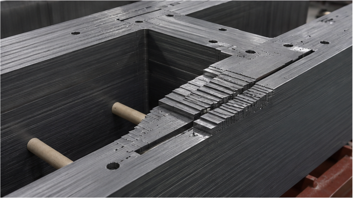
Lamination joints are one part of the magnetic circuit; a test anomaly still requires investigation before a manufacturing cause is assigned.
Once the measurement is credible, a persistent deviation may justify review of the magnetic design and assembly records. Relevant items include steel specification, lamination condition, joint assembly, clamping and unintended conductive paths. A damaged interlaminar coating or an unintended electrical bridge can change local current paths and heating. A drawing alone cannot demonstrate the condition of the finished assembly.
From a manufacturing-review perspective, the useful question is not simply whether the specified steel was purchased. It is whether the completed magnetic circuit preserves the intended geometry and insulation. Request records that relate to the particular unit or batch under review. Avoid accepting a general factory photograph as proof of that unit's construction quality.
Use additional investigations proportionately. A single abnormal current measurement does not justify asserting shorted turns, a core fault or a transport problem without supporting evidence. Equally, a close-to-limit result should not be dismissed merely because the transformer has passed unrelated tests.
The purchaser's technical schedule should separate guaranteed no-load loss, load loss and any total-loss requirement. Identify the governing standard edition, contractual tolerances, correction method and decision rule. IEC 60076-1:2011 (Power Transformers – Part 1: General) is the general power-transformer reference; the actual purchase specification and applicable documents must establish how the particular result is assessed.
Do not combine a contractual tolerance and measurement uncertainty into an informal extra margin. They answer different questions. If the measured result is near the boundary, the report must explain the agreed decision method instead of leaving the witness to negotiate an undocumented adjustment. Commercial treatment of losses also needs to be agreed before the test, not improvised at shipment release.
FAT finding | What should be confirmed | Recommended disposition |
|---|---|---|
Loss comfortably within the agreed criterion | Valid setup, traceable readings and complete corrections. | Accept this test item when the documentary requirements are satisfied. |
Result close to the decision boundary | Uncertainty statement and the pre-agreed conformity decision rule. | Resolve the decision transparently; do not add an undocumented allowance. |
Unstable or inconsistent repeated readings | Source, instrument ranges, connections and test sequence. | Hold the test item until the cause is identified and a valid result is recorded. |
Persistent excess loss or unexplained current pattern | Confirmed measurements and design or manufacturing investigation. | Raise a documented nonconformity and agree corrective action and retesting. |
No-load loss matters whenever the transformer remains energized, even when useful load is small. Compare options using the anticipated energized hours, not merely the site's production hours. A standby transformer left energized can accumulate core-loss energy while carrying little load. Conversely, an intentionally de-energized spare has a different operating profile.
For an illustrative difference of 0.4 kW over 8,000 energized hours, the annual energy difference is 3,200 kWh. This is arithmetic, not a claim about any Zisheng Electric product. Apply the project's actual tariff and evaluation method separately. Our discussion of no-load and load-loss trade-offs provides the broader operating context; this FAT guide focuses on whether the measured value is trustworthy.
A lower no-load loss is not sufficient grounds to ignore load losses, cooling, dimensions or the required duty. Keep the complete distribution-transformer design inputs in the comparison. Otherwise, a purchasing team can optimize one line in the schedule while creating a problem elsewhere.
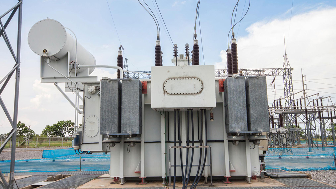
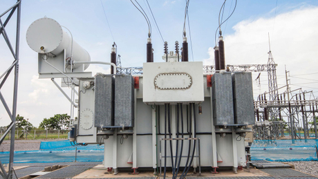
An outdoor installation may remain energized through light-load periods; the project operating plan determines the annual no-load energy exposure.
A specification for a 200 kVA oil-immersed substation transformer should state the required loss guarantees for that exact electrical design. Do not transfer a figure from a different voltage ratio, frequency or core arrangement just because the capacity matches. Catalogue information is a starting point; the approved datasheet and test report are the controlling project records.
The same discipline applies to a 150 kVA three-phase pad-mounted transformer. Its enclosure and connection arrangement change the installation interface, but they do not remove the need for a clearly defined no-load test basis. Confirm the purchased configuration, accessories and terminal identification before the witness signs the report.
The final record should identify the transformer serial number, approved datasheet revision, test date, personnel, connection diagram, tapping, measured voltage and frequency, active power and current values, corrections and resulting declared figures. Include the measurement-chain identification, relevant calibration evidence, uncertainty statement and acceptance decision. The report should distinguish original observations from calculated or corrected values.
Keep anomalous results and their disposition traceable. A retest report should refer to the investigation or corrective action and identify the configuration used. A clean final table without that history can leave the owner unable to interpret later measurements or resolve an acceptance dispute.
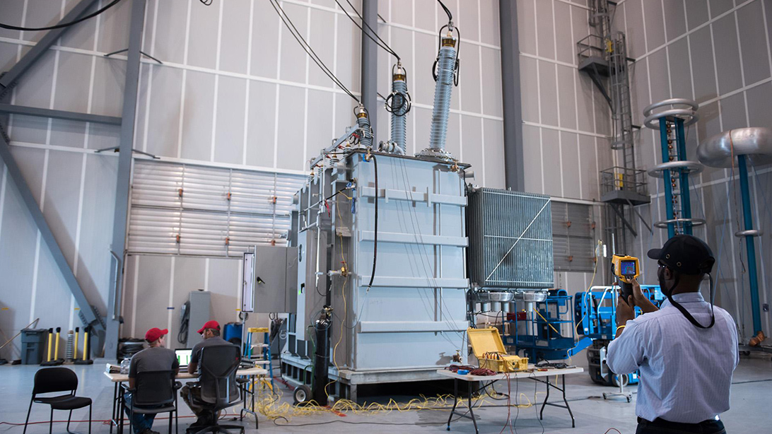
FAT documentation should identify the unit, test arrangement and accepted results rather than relying on photographs alone.
Send Zisheng Electric the transformer datasheet, single-line diagram, specified loss guarantees, expected energized hours and FAT witness requirements. Include the voltage level, frequency, tap range, environmental conditions and governing project specification. These inputs allow the review to connect a proposed oil-immersed or pad-mounted transformer with its actual operating duty and acceptance evidence.
The goal is a test result that means the same thing to the designer, test engineer and purchaser. Zisheng Electric can provide technical matching based on project capacity, voltage level, environmental conditions and technical specifications. Our engineering team will review the requirements and respond to project inquiries within 24 hours.