Technical Specifications
Rated Power | 150 kVA |
Rating Primary Voltage | 4.16-34.5kV or customized |
Secondary Voltage | 480GrdY/277 |
Frequency | 50/60Hz |
Vector Group | Dyn1/Yyn0/Dyn11/Dyn5 |
Winding Material | Aluminum/Copper |
Efficiency | As IEEE,Doe 2016,CAS Std or Customized |
Impedance Voltage | Nominal 3.5% or Customized 1.1-5.75% |
Altitude | ≤1,000m or Customized |
Color | ANSI 70 Light gray/Munsell 7GY3.29/1.5 or customized etc |
Tank material | Mild Steel, 304 Stainless Steel |
Insulating Oil Weight | 350L |
Total Weight | 2400 kg |
Outline Dimensions(L×W×H)in. | 1250×1480×1750 (mm) |
Accessories
Lifting Lug | ELSP Fuse |
Hinged Door | BAY-O-NET Fuse |
Parking Bracket | Tap Changer |
Tank Cover | Oil Level Gauge |
L.V Bushing (4-Hole ) | Pressure Relief Valve |
Two/Four Position Load break Switch | Vacuum Pressure Gauge |
HV Grounding Copper Bar | Terminal Block |
Temperature Indicator | Door Handle |
H.V Bushing Well(15kV) | Ground Strap |
Grounding Copper Bar | Nameplate |
1"'Drain Valve With 3/8" Sampler | IR Window |
1" Upper Fill Valve Filter Press Connection | Terminal Box |
Non-PCB decal | High Voltage Warning Signs |
150kVA Three Phase Pad Mounted Transformer
The 150kVA three phase pad mounted transformer provides broad customization to accommodate unique voltage, environmental, and operational needs. Primary voltage selections include grounded wye or delta configurations from 4160V to 34500GrdY/19920, with single or dual voltage designs and HV tap changers (±2×2.5% or greater) for precise regulation during load changes. Secondary voltages offer flexible options like 208Y/120V, 480Y/277V, 240 Delta/120 center-tap, 600Y/347V, or project-specific low-voltage outputs. Winding choices feature aluminum for balanced cost and performance or high-grade copper for enhanced conductivity and thermal endurance. Cooling/insulation fluids range from conventional mineral oil (ONAN) to biodegradable FR3 ester for superior fire protection and sustainability in populated or restricted areas. Enclosure configurations support radial feed with standard bushings, loop feed with parking stands and standoffs, plus integrated fusing (bayonet, current-limiting, or weak-link), surge arresters, oil level indicators, pressure/vacuum gauges, drain/sampling valves, and optional elbow arresters.
Further tailoring includes elevated BIL levels (95kV–150kV or higher) for surge-prone locations, reduced noise designs for residential-adjacent sites, custom enclosure finishes (colors, stainless steel tanks for coastal durability), and advanced security elements like penta-head bolts, padlockable doors, and anti-vandalism reinforcements. Smart features such as temperature probes, dissolved gas analysis ports, or remote monitoring compatibility support intelligent grid integration. All custom variants maintain compliance with IEEE C57.12.34, ANSI C57.12.00, CSA, and DOE 2016 efficiency mandates, preserving a low-profile, space-efficient design for simple pad installation, robust performance in varied climates, and optimal energy savings in commercial buildings, schools, hospitals, and utility expansions.
150kVA Three Phase Pad Mounted Transformer
Prior to packing, the 150kVA three phase pad mounted transformer undergoes meticulous preparation, including dielectric oil quality verification (for filled shipments), nitrogen purging in dry configurations to safeguard against humidity and corrosion, and protective shielding of bushings, valves, gauges, and fittings using impact-resistant covers and secure strapping to endure transport vibrations. The tank exterior applies temporary anti-corrosion treatments and wraps on critical surfaces, while all detachable accessories receive individual packaging and labeling for easy identification and damage prevention.
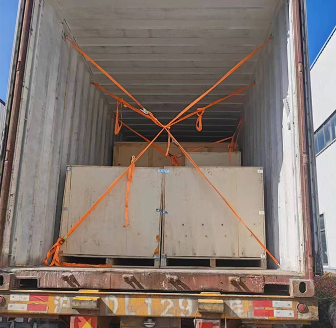
Packing involves custom-engineered wooden crates or reinforced skids sized precisely to the unit's dimensions, reinforced with steel strapping, internal supports, and weight-distributing blocks to accommodate the typical dry weight of 1800–2400 lbs (higher when oil-filled). Export shipments comply with ISPM 15 heat-treated wood standards, incorporating vapor barrier films, desiccant materials, and humidity indicators for moisture control. Oil-filled deliveries include reinforced seals around fittings, leak-absorbent padding, and adherence to international hazardous substance rules for insulating fluids, complete with regulatory labeling and supporting paperwork.
Shipping strategies focus on secure, efficient delivery tailored to location and requirements. Domestic U.S. shipments use specialized heavy-haul carriers with lowboy trailers, secure tie-down systems, and route planning for oversize loads. International transport combines road haulage to ports, ocean freight in 20ft/40ft open-top or flat-rack containers (or break-bulk arrangements for multiple units), and final destination trucking. Full insurance coverage, traceable GPS monitoring, and comprehensive documentation (packing lists, test certificates, installation guides) ensure transparency and smooth logistics.
At the delivery site, immediate inspection for any transit-related issues, seal checks, and oil level confirmation is advised prior to unloading. Professional crane or forklift handling with spreader bars is essential to avoid tank deformation. Our logistics coordination includes freight quoting, export compliance (certificates of origin, commercial invoices), and customs facilitation to reduce delays, delivering the transformer prepared for prompt concrete pad placement, cable termination, and energization with maximum reliability.
150kVA Three Phase Pad Mounted Transformer
The progress test for the 150kVA Three-Phase Pad Mounted Transformer is conducted to ensure that the transformer meets all technical and safety specifications throughout the manufacturing process. This includes testing at various stages of production, starting from the core assembly to the final testing of the complete unit. Key tests typically include:
Dielectric Strength Test: Ensuring the insulation system is capable of withstanding the required voltage levels.
Winding Resistance Test: Verifying the resistance of the windings to ensure proper conductivity and low loss.
Temperature Rise Test: Confirming that the transformer operates within the acceptable temperature limits during load conditions.
Oil Test (if applicable): Checking the oil quality for proper dielectric properties and ensuring the oil level is adequate.
These tests are performed to verify that the transformer will operate reliably and safely under normal operating conditions. Any issues identified during the progress test are addressed before the transformer is delivered to the customer.
All transformer will be test after finished the production, test items as below:
♦ Insulation Power Factor
♦ Ratio, Polarity, and Phase Relation
♦ Winding Resistance
♦ Impulse Tests
♦ On load Loss Test
♦ No Load Loss Test
♦ Transformer Turns Ratio/TTR (All Tap Voltages)
♦ Impedance Voltage & Load Loss (Rated Voltage)
♦ Polarity, 1-Ph / Phase Relation, 3-Ph (Rated Voltage)
♦ Excitation & No-Load Loss (Rated Voltage)
♦ Applied Voltage
♦ Induced Voltage
♦ Lightning Impulse
♦ Insulation Resistance (Rated Voltage)
♦ Temperature Rise
♦ Dielectric Withstand (Hipot)
Dielectric withstand testing applies separate-source potential and induced voltage at increased levels without flashover or abnormal discharge. Impedance voltage and load loss are measured under short-circuit to match guaranteed figures. Oil properties including breakdown voltage, moisture, and acidity are tested for filled units. Functional demonstrations confirm fuse blowing, pressure relief operation, indicator accuracy, valve performance, and bushing condition. Additional tests such as sound level assessment, simulated temperature rise, or special impulse may be conducted per contract. Results are compiled in formal reports, open to client/third-party witnessing, certifying full adherence to IEEE C57.12.34, C57.12.00, ANSI, and efficiency regulations before shipment authorization, assuring superior field reliability and performance. Winding resistance DC measurements are taken and temperature-adjusted. No-load loss, excitation current, and core performance data at rated voltage validate DOE 2016 efficiency and low-noise criteria.
Purpose of Testing
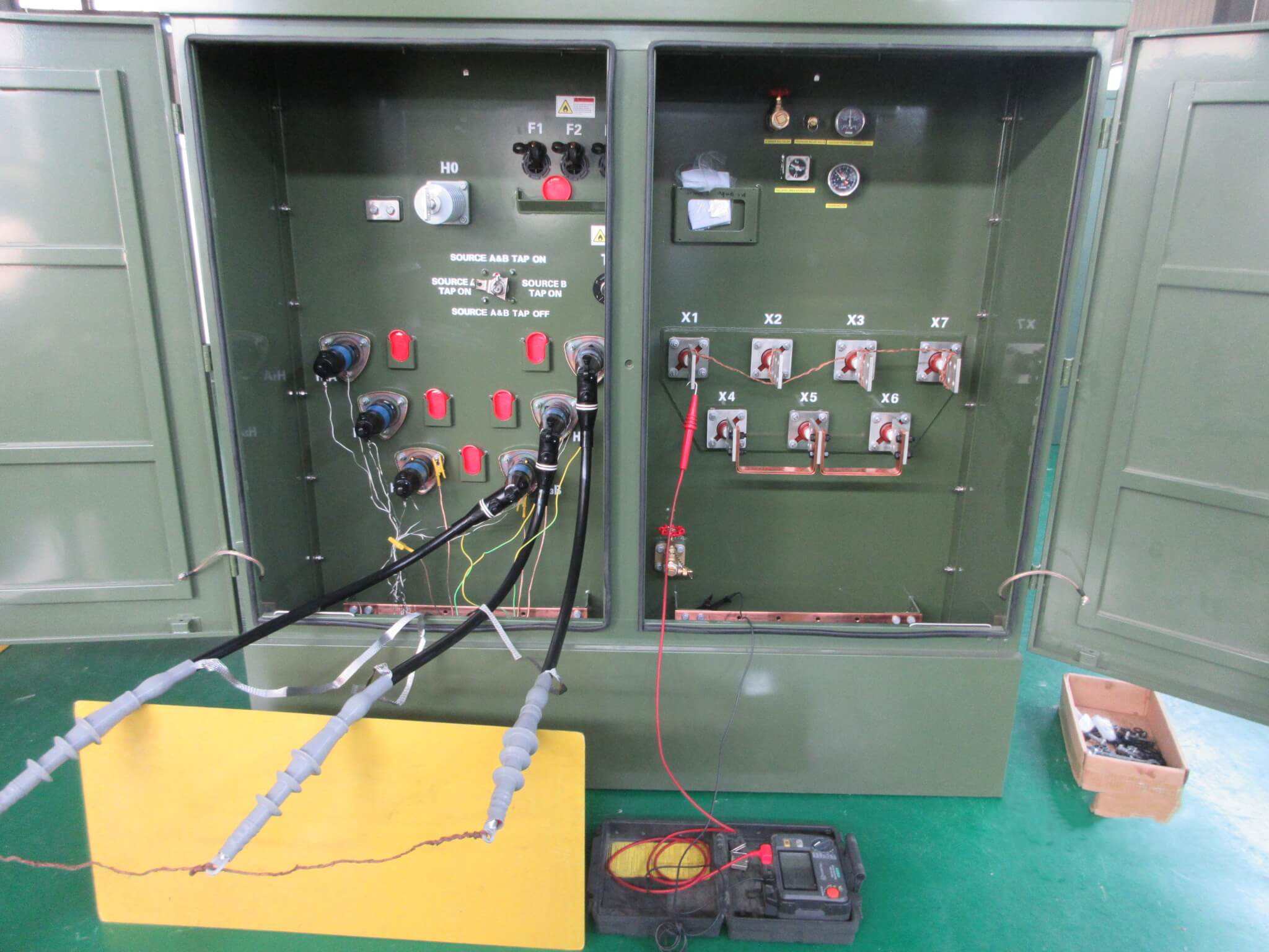
The purpose of the transformer turns ratio (TTR) test is to confirm whether the voltage ratio between each tap of the transformer meets the design requirements and ensure that the transformer winding is connected correctly. By measuring the voltage ratio of each tap, it is possible to detect whether there is a fault or deviation in the transformer winding.
Testing Equipment
TTR tester: such as Doble, Megger, Omicron and other brands of transformer winding ratio tester.
Voltage source: usually AC 10 V to 30 V , used to test different voltages for each tap.
Temperature and humidity meter: used to record environmental conditions during the test to ensure test accuracy.
Current probe: used to measure the load current of the winding and ensure the accuracy of the test results.
Pre-Test Preparation
Disconnect all transformer tap-changers from the power supply and ensure that all equipment is properly grounded and discharged.
Perform the test under suitable environmental conditions: relative humidity below 75% and no rain (recommended temperature: 20-30°C). Avoid high humidity or bad weather that may affect the test accuracy.
Test Progress
Perform the test under suitable environmental conditions: relative humidity below 75% and no rain (recommended temperature: 20-30°C). Avoid high humidity or bad weather that may affect the test accuracy.
Measure and Record
Start the test and record the following parameters:
The voltage ratio between the windings
Deviation of the measured value from the rated ratio
Temperature Correction
If necessary, perform temperature correction on the measured turns ratio data (especially when testing at higher or lower temperatures). Generally, the standard reference temperature for temperature correction is 20°C.
Repeat Testing (if necessary)
Test the transformer's windings of different voltage levels (high voltage, medium voltage, and low voltage) separately to ensure that the turns ratios of all windings are normal.
Evaluation Criteria (Reference)
Turns ratio error ≤ 0.5% (pass)
0.5% < Turns ratio error ≤ 1% (caution)
Turns ratio error > 1% (further inspection or corrective action required)
*These comprehensive tests ensure that each transformer meets performance standards and operates reliably under various conditions.