Please Choose Your Language
Procuring major electrical equipment represents a massive capital expenditure for any industrial facility. This specific decision directly dictates plant uptime, safety, and daily operational efficiency. You simply cannot afford unexpected power disruptions when running heavy manufacturing machinery. At this stage, your engineering team has already mapped out the facility load profile. The final decision now hinges on finalizing precise technical specifications. You must choose the correct cooling method, evaluate insulation types, and carefully vet reliable manufacturers.
This guide bypasses basic definitions to focus entirely on technical evaluation criteria and compliance standards for industrial power applications. You will learn how to navigate complex sizing validations and compare solution categories effectively. We also explore the core technical specifications needed to future-proof your power infrastructure and mitigate supply chain risks.
Match Type to Environment: Oil-immersed units are cost-effective for outdoor industrial use, while cast-resin dry-type transformers are mandatory for stringent indoor fire-safety zones.
Size for Harmonics & Peak: A standard 2500kVA rating must account for non-linear loads (like VFDs) and inrush currents without risking premature degradation.
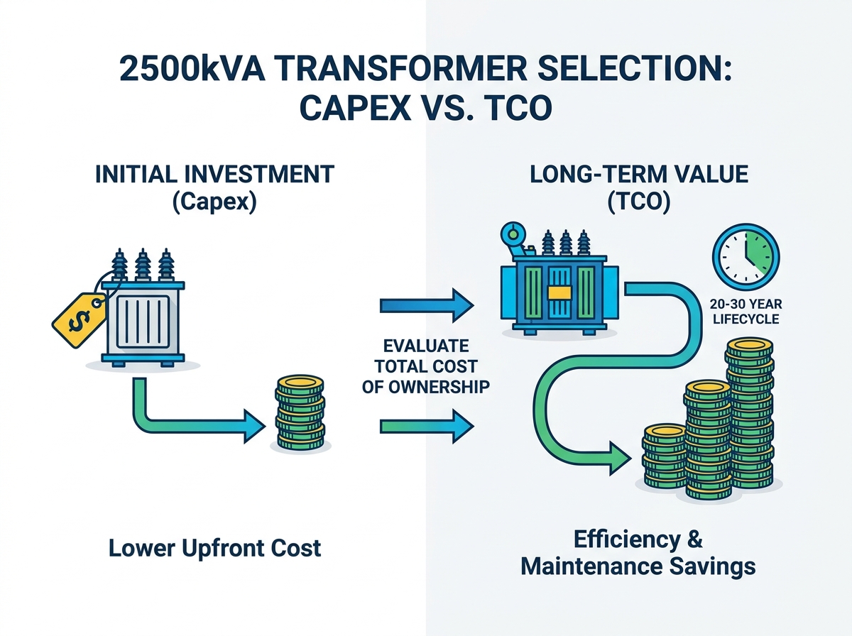
Prioritize Loss Evaluation: Evaluating no-load and load losses against standard efficiency regulations (e.g., DOE 2016 or EcoDesign Tier 2) drastically alters the 20-year TCO.
Demand Factory Acceptance Testing (FAT): Shortlist "source factories" that provide transparent testing protocols, certified impedance values, and traceable material sourcing.
Evaluating your plant load profile requires more than simple addition. You must account for dynamic operational shifts, peak demands, and the nature of the connected equipment. Properly sizing a 2500kVA Transformer ensures optimal performance and prevents premature insulation failure.
You must establish a strong operational baseline. Industry standards recommend maintaining a 20% safety margin for continuous loads. If your plant requires roughly 2000kVA of continuous power, upgrading to a 2500kVA rating provides necessary headroom. This buffer protects the unit during brief peak demand periods. It prevents localized overheating within the windings. Operating continuously at 100% capacity accelerates thermal degradation. Leaving a 20% margin extends the equipment lifespan significantly.
Modern industrial plants rely heavily on non-linear loads. You must identify the presence of Variable Frequency Drives (VFDs), heavy motor starting sequences, or large welding equipment. These devices introduce harmonic distortion into the electrical system.
Identify Harmonic Sources: Document all VFDs, rectifiers, and arc furnaces on your network.
Evaluate K-Factor Requirements: Standard units cannot handle severe harmonic heating. You may need a K-factor rated unit.
Address Inrush Currents: Large industrial motors draw massive starting currents. Ensure the transformer withstands these frequent spikes without voltage sagging.
Harmonics distort the sine wave and cause excessive eddy current losses. This generates dangerous internal heat. Specifying appropriate harmonic mitigation prevents unexpected failures.
Your sizing strategy must factor in projected plant expansions over the next 5 to 10 years. Undersizing poses severe risks. If you exceed the rated capacity, you face immediate overheating and potential catastrophic failure. Conversely, extreme oversizing incurs an efficiency penalty. Transformers operating at very low loads suffer from poor efficiency due to constant core losses. The 2500kVA rating often serves as the perfect middle ground for medium-to-large industrial facilities planning moderate expansion.
Selecting the right insulation and cooling medium dictates where you can install the equipment safely. The environment directly influences this decision. We divide these solutions into two primary categories.
Oil-immersed units serve as the backbone of outdoor industrial power distribution. They utilize mineral oil or synthetic ester fluids for both insulation and cooling. The liquid medium circulates through the core and windings, transferring heat to external radiators.
Advantages: These units typically feature lower initial procurement costs. They offer superior heat dissipation capabilities compared to dry alternatives. This excellent cooling translates to a higher temporary overload capacity. They handle harsh outdoor elements effortlessly.
Drawbacks: Environmental regulations demand strict containment measures. You must construct concrete bunds or firewalls to contain potential oil leaks. Additionally, they require regular maintenance. You must perform Dissolved Gas Analysis (DGA) testing to monitor the oil condition over time.
Cooling Classes:
ONAN (Oil Natural Air Natural): Relies entirely on natural convection. Heat rises, moving oil through the radiators while natural airflow cools the exterior.
ONAF (Oil Natural Air Forced): Incorporates external fans on the radiators. This forced airflow drastically improves cooling. It allows you to push the capacity safely beyond the base rating during peak production periods.
Cast-resin dry-type transformers encase the high-voltage windings in a solid epoxy resin. This design eliminates liquid coolants entirely. They are engineered specifically for indoor environments and critical fire-safety zones.
Advantages: The epoxy resin is inherently self-extinguishing. This eliminates fire hazards and zero oil-leakage risks. Maintenance requirements drop significantly since there is no liquid to test. Facilities often benefit from lower insurance premiums when installing these indoors.
Drawbacks: They carry a higher upfront procurement cost. The physical footprint is generally larger because air acts as a less efficient insulator than oil. They also demand strict ambient temperature controls and robust indoor ventilation systems to prevent overheating.
Cooling Classes:
AN (Air Natural): Relies on standard ambient air convection for cooling.
AF (Air Forced): Uses cooling fans directed at the coils. This configuration can increase the nominal capacity temporarily to handle sudden load spikes.
Feature | Oil-Immersed | Dry-Type (Cast Resin) |
|---|---|---|
Primary Application | Outdoor, Heavy Industry | Indoor, Commercial, High-Risk |
Cooling Efficiency | Excellent (Liquid) | Moderate (Air) |
Maintenance Needs | High (Oil sampling, DGA) | Low (Visual inspection, dusting) |
Fire & Spill Risk | Requires containment bunds | Self-extinguishing, zero spills |
Footprint | Compact core, large radiators | Larger enclosure required |
Once you determine the appropriate category, you must define the exact electrical parameters. These specifications ensure the equipment integrates seamlessly into your existing grid. Securing the right 2500kVA Transformer involves vetting several highly technical metrics.
Voltage ratios form the fundamental purpose of this equipment. You must align the primary voltage with your utility grid supply. Common high-voltage inputs include 35kV, 11kV, or 13.8kV. The secondary voltage must match your plant distribution network exactly. Standard industrial low-voltage outputs typically run at 400V or 480V. Mismatched voltages cause immediate equipment failure. Ensure your engineering team verifies the utility tap settings available for slight grid fluctuations.
Impedance dictates how the unit responds under short-circuit conditions. It acts as an internal bottleneck for electrical current. Typical industrial units at this capacity range from 5.5% to 6.5% impedance. You must balance two competing factors here. A higher impedance limits destructive short-circuit fault currents, protecting downstream switchgear. However, higher impedance also increases voltage drop during normal operation. You must coordinate this value closely with your plant's short-circuit study to ensure protective relays operate correctly.
The vector group defines the winding connections and the phase shift between the primary and secondary sides. For industrial loads, standardizing on the Dyn11 vector group is highly recommended.
D (Delta Primary): Traps third harmonics circulating within the primary loop, preventing them from feeding back into the utility grid.
yn (Star Secondary with Neutral): Provides a solid neutral connection for single-phase loads.
11 (Phase Shift): Indicates a 30-degree phase shift.
Dyn11 excels at handling unbalanced phase loading. It effectively suppresses third harmonics generated by industrial machinery.
The choice of winding material sparks frequent debate among engineers. You need an objective comparison based on your facility layout and budget.
Copper offers superior thermal conductivity and lower electrical resistance. Copper windings result in a smaller physical footprint. Copper also boasts higher mechanical strength, better withstanding the physical forces of short circuits. However, it commands a premium price.
Aluminum costs significantly less upfront. To achieve the same electrical conductivity, aluminum windings must be physically larger. This increases the overall dimensions of the core and enclosure. While modern manufacturing techniques make aluminum highly reliable, copper generally provides better longevity in extreme environments.
Modern industrial facilities must prioritize energy efficiency and environmental safety. Relying on outdated specifications guarantees long-term performance issues. You must scrutinize energy losses strictly.
Global energy regulations dictate stringent minimum efficiency requirements. You must ensure your specified unit meets or exceeds regional mandates. In the United States, equipment must comply with DOE 2016 standards. In the European Union, the EcoDesign Tier 2 directive applies. These regulations force manufacturers to utilize higher-grade grain-oriented silicon steel in the core. Compliance ensures your equipment wastes less energy as heat. Non-compliant units face heavy regulatory scrutiny and cannot be legally installed in many jurisdictions.
Energy losses occur continuously, translating into wasted power and excess heat. You must evaluate the operational impact of two specific loss categories.
No-load losses (core losses) occur constantly as long as the primary side remains energized. This happens even if the plant shuts down for the weekend. These iron losses stem from magnetizing the core. Load losses (copper losses) vary based on how much power the plant draws. They occur due to the electrical resistance in the windings.
Calculating the long-term energy waste over a 20-30 year lifecycle reveals the true efficiency of the unit. A cheaper model with high no-load losses will generate excessive heat continuously. This forces your ambient cooling systems to work harder, accelerating thermal degradation of the insulation.
Harsh plant environments demand robust safety compliance. If you choose an oil-immersed unit, evaluate ester-based biodegradable fluids. Natural esters (like FR3) offer a much higher flash point than traditional mineral oil, vastly improving fire safety. They also biodegrade rapidly if a spill occurs, mitigating environmental fines.
For dry-type units, scrutinize the enclosure ratings. You must specify appropriate IP (Ingress Protection) or NEMA ratings. Dusty industrial plants require IP54 or NEMA 3R enclosures to prevent conductive particulate matter from settling on the high-voltage coils.
Even the most perfect technical specification fails if the supplier cannot deliver. The industrial supply chain carries inherent risks. You must evaluate vendors rigorously to ensure quality manufacturing and reliable delivery.
Many online industrial suppliers act merely as trading companies or resellers. You must verify a supplier's actual manufacturing capabilities. Deal directly with "source factories" whenever possible. Request documentation of their ISO 9001 (Quality) and ISO 14001 (Environmental) certifications. Ask for virtual factory tours or facility audits. A true manufacturer controls the entire process, from core cutting to vacuum drying the windings.
Never accept delivery without reviewing comprehensive FAT reports. These mandatory tests prove the unit meets your specific engineering criteria.
Routine Tests: Include winding resistance measurement, voltage ratio checks, and vector group verification.
Type Tests: Include temperature rise testing. This proves the cooling system handles the rated load without exceeding thermal limits.
Special Tests: Include lightning impulse testing. This verifies the insulation can withstand severe voltage surges.
Demand transparent testing protocols and certified impedance values before the unit leaves the factory floor.
Managing production schedules prevents costly project delays. A custom-built heavy industrial unit takes time to manufacture. Assess the vendor's shipping framework carefully. You are transporting a piece of equipment weighing 5 tons or more. Verify their crating methods and secure freight forwarding partners. Confirm whether the unit ships filled with oil or under nitrogen gas pressure. Clear logistics prevent damage during transit.
Define acceptable warranty periods clearly in your procurement contract. A standard industrial warranty typically covers 18 to 24 months from the date of energization. More importantly, assess the availability of spare parts. You must have quick access to replacement bushings, cooling fans, and tap changers. Strong post-sale support ensures minor component failures do not cause prolonged plant shutdowns.
Selecting the optimal power infrastructure requires balancing upfront procurement considerations with long-term operational performance. You must weigh initial investments against the realities of continuous energy losses, thermal degradation, and maintenance demands. An undersized or inefficient unit disrupts plant operations and generates excessive, damaging heat.
We advise decision-makers to finalize their environment type first, definitively choosing between indoor dry-type or outdoor oil-immersed solutions. Next, compile a highly specific load profile detailing harmonics and peak demands. Finally, engage directly with certified source manufacturers. Request custom engineering quotes that detail precise no-load and load loss values. Taking these rigorous steps guarantees a reliable, safe, and highly efficient power supply for your facility's future.
A: Current average supply chain timelines range from 8 to 16 weeks. This timeline fluctuates based on your chosen winding material, specialized cooling requirements, and the factory's production backlog. Custom cast-resin dry-type units often take slightly longer than standard oil-immersed models due to the complex epoxy curing process. Always confirm lead times during the initial quoting phase.
A: Physical footprints vary drastically by type. A standard oil-immersed unit requires about 2.5 by 2 meters of pad space, plus clearance for radiators and containment bunds. A dry-type unit demands a larger protective enclosure, often exceeding 3 by 2.5 meters. You must also maintain strict clearance around the enclosure to ensure adequate airflow and safe maintenance access.
A: You can expect a baseline lifespan of 20 to 30 years. However, this longevity remains heavily contingent on operational factors. Proper continuous load management, preventing severe harmonic distortion, and maintaining controlled ambient temperatures extend lifespan. Routine maintenance, such as regular DGA testing for oil units and vacuuming dust from dry-type coils, is absolutely critical for reaching this 30-year benchmark.
A: Standard De-Energized Tap Changers (DETC) suffice for most industrial plants with stable grid connections. You adjust these only when the unit is powered down. You should only specify an expensive On-Load Tap Changer (OLTC) if your facility experiences highly volatile utility feeds and requires constant, active voltage regulation while the plant remains fully operational.