Views: 0 Author: Zisheng Electric Publish Time: 2026-09-27 Origin: Site
Zisheng Electric approaches transformer marshalling cabinet inspection as a check of the equipment that connects factory-built accessories to the installation team. A cabinet can look tidy while containing the wrong heater supply, an inaccessible terminal or a wire identifier that disagrees with the approved drawing. These details can delay commissioning even when the transformer’s main electrical tests are satisfactory.
This factory quality review is intended for EPC engineers, inspection agencies and buyers reviewing the supplied cabinet before shipment. Its focus is construction and verification: what is fitted, how it is identified, whether it can be connected and maintained, and which records show that the agreed functions were checked. The approved project specification and component instructions remain the basis for acceptance.
Start with the cabinet equipment tag and its drawing index. Identify the terminal boxes, cooling-control compartments and separately supplied panels included in the inspection. A remote station control panel should not quietly be counted as part of the transformer supplier’s scope, nor should a transformer-mounted auxiliary box disappear between purchase packages.
List the functions actually included. Some cabinets mainly collect accessory contacts. Others contain cooling starters, auxiliary protection, transducers or communication equipment. Inspection effort should follow the supplied design. A generic checklist with every possible function can produce meaningless tick marks, while a short checklist based on the approved circuit schedule makes omissions visible.
Have the general arrangement, schematic, terminal plan, bill of materials, auxiliary-load schedule and approved changes available together. Record their revisions on the inspection sheet. If the schematic changed after wiring started, identify the affected circuits before inspection proceeds. A drawing stamped approved does not establish that it represents the cabinet now standing on the workshop floor.
The wider digital monitoring specification should already define which signals and devices are required. This inspection checks whether that accepted scope has been translated into a usable physical assembly. It does not reopen the sensor-selection exercise or approve the site control system.
Open doors and removable covers using the normal service arrangement. Review access to terminals, protective devices, heater controls and components expected to be replaced. An attractive layout may become impractical once field cables enter the gland plate. Compare the proposed cable sizes, entry directions and bending space with the terminal position, rather than judging an empty cabinet in isolation.
Check that component identification remains visible with wiring-duct covers fitted. Confirm that access to a routine maintenance item does not require disturbing unrelated wiring without an agreed reason. Spare terminals and reserved space should be identified as such, with their allocation consistent across the drawing and installed assembly. Empty space alone is not evidence that future connections are feasible.
Door operation, hinges, locks and retention arrangements also deserve attention. Confirm the installed position allows the intended opening and inspection access. The cabinet may be inspected on a bench but delivered on a tank, where a radiator, pipe or structural member changes the available space. Use the assembly drawing to assess the delivered configuration.
IEC 60529 describes degrees of protection provided by enclosures through the IP Code. Where the purchase specification cites it, check the required edition and the evidence applicable to the offered enclosure. Do not treat a label on an empty enclosure as confirmation of every cable entry, door modification or installed accessory in the completed cabinet.
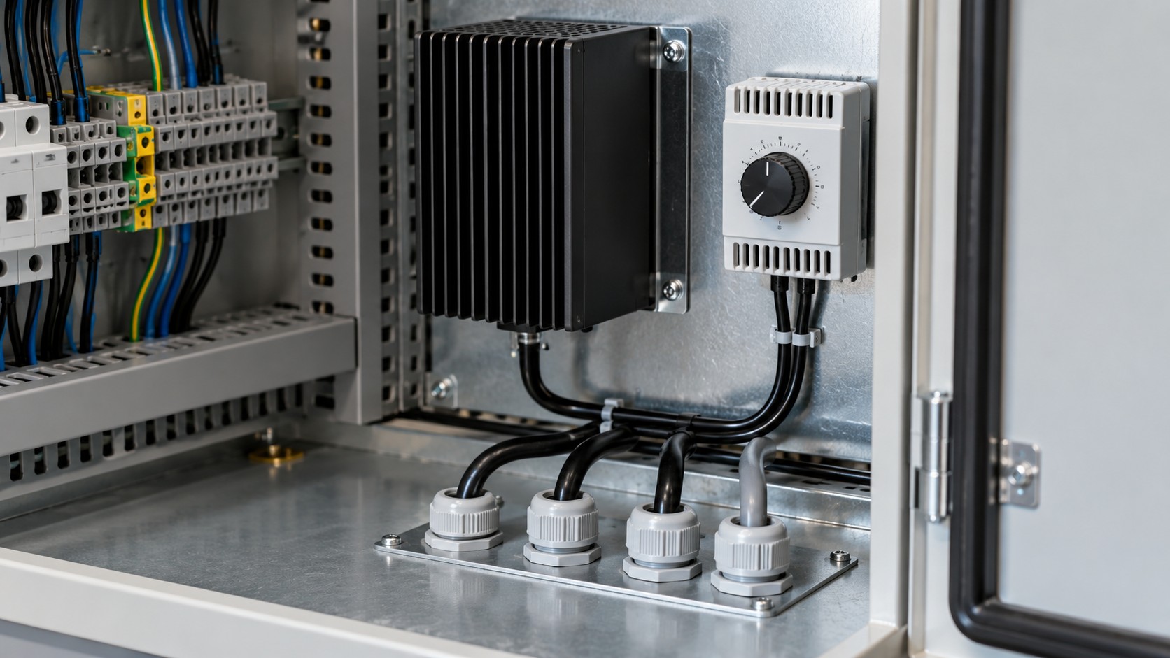
Review seals, unused openings, gland provisions and the intended treatment of site-installed cables. Specify who supplies and installs the final glands or blanking devices. Environmental suitability also involves the selected materials, corrosion exposure and moisture-control arrangement; these questions should be reviewed explicitly instead of being hidden behind a single enclosure designation.
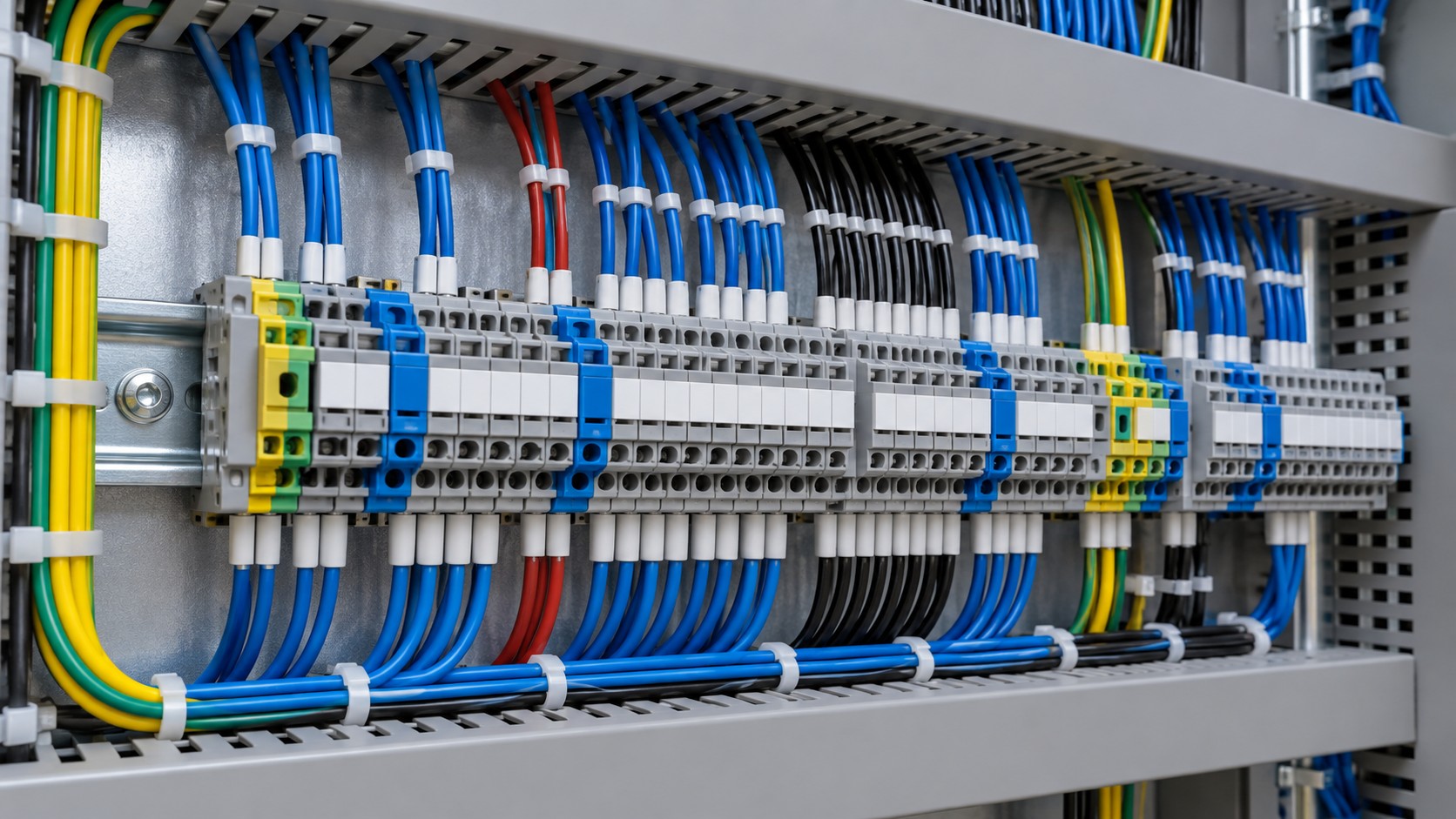
Wire identification should allow an inspector to follow a circuit without relying on the memory of its assembler. Compare device tags, terminal numbers, core identifiers and destination references. Use the approved inspection procedure to establish how wiring verification is recorded and which circuits require witnessed checks. Photographs are useful supporting records but do not demonstrate electrical continuity.
Review conductor termination against the connector manufacturer’s instructions. The relevant details include conductor type, accepted cross-section, preparation, ferrule or lug arrangement and specified tightening method. Do not impose one universal torque across different terminal families. A recorded tightening value is useful only when it refers to the correct connection and approved requirement.
Inspect routing around sharp edges, moving doors, heat sources and removable parts. Check support, strain relief and the separation required by the design for different circuits. The aim is to avoid damage and maintain clarity through transport and service, not simply to achieve symmetrical wire bundles. Corrections should retain the identification needed for subsequent testing.
Match physical wire and terminal identification to the current drawing.
Mark which side of each terminal is intended for factory wiring and which for site wiring. Confirm the space needed for the specified external conductors and test access. Where disconnecting or test terminals are supplied, their type and normal service arrangement should agree with the approved design. Special circuits require their own competent review; a general cabinet checklist cannot substitute for protection engineering.
A practical inspection record can reference a terminal range and its drawing sheet, then list individual discrepancies separately. This is more useful than a statement that “all wiring is correct” without identifying what was examined. The installation team should be able to reconcile the delivered terminal plan with the actual cabinet without interpreting workshop abbreviations.
Record every incoming auxiliary supply, its nominal characteristics and the loads it serves. Separate cabinet heaters, lighting, control circuits, cooling equipment and electronic devices where the design does so. Verify the component ratings against the accepted supply schedule. An AC heater circuit and a DC control circuit may share an enclosure, but their requirements should not be inferred from one another.
Heater inspection includes location, clearances, wiring protection, control device and the manufacturer’s installation instructions. Confirm the intended operating philosophy: continuous service, thermostatic control or another approved arrangement. Do not assume a heater fitted inside the cabinet is available during transport or site storage. Its effectiveness depends on the supply and preservation plan actually provided.
Ask who supplies temporary auxiliary power if the cabinet reaches site before station services are available. That responsibility belongs in the delivery and storage documents. The factory should identify what must remain powered, any permissible alternatives and the conditions under which the equipment can be stored. These details need equipment-specific confirmation rather than a generic instruction to keep everything dry.
Check the heater installation together with its supply and preservation requirements.
Inspection item | Evidence to compare | Why it affects acceptance | Action when inconsistent |
|---|---|---|---|
Incoming supplies | Auxiliary-load schedule, schematic and component ratings | An incorrect supply assumption can disable several functions together | Resolve the design basis before functional testing |
Field terminal access | Terminal plan, cable schedule and cabinet layout | Site conductors need workable termination and maintenance space | Obtain an accepted layout correction |
Heater arrangement | Component instructions, control circuit and preservation requirements | Installed hardware alone does not establish moisture control | Clarify supply, controls and storage responsibility |
Wire identification | Physical markers and current schematic | Ambiguous identity can cause incorrect field connections | Correct markers and drawings together, then verify |
Enclosure completion | Required protection, glands, seals and approved modifications | Unfinished openings can invalidate the intended installed arrangement | Record remaining work and its responsible party |
Functional corrections | Discrepancy record, revised circuit and repeat-test evidence | A repair may affect previously accepted functions | Define and complete the affected verification scope |
Agree the test scope before the witness visit. Identify the functions that can be checked with the cabinet alone and those requiring transformer accessories, external panels or site equipment. A simulated input can prove part of a circuit, but the report should name the simulation boundary. It should not imply that an absent field device or control-room destination has been tested.
Functional checks should follow the approved procedure and be performed by competent personnel under the required safety controls. Record the relevant supply condition, input, expected response and observed result. For cooling circuits, for example, the agreed scope may distinguish a control indication from operation of connected equipment. Specify which result is required instead of using the single word “operational.”
Where loss-of-supply or abnormal-state checks are part of the agreed scope, record the intended response and restoration condition. Do not improvise these checks during a customer visit. The design authority should define the expected behavior, while the test team establishes a controlled method that protects equipment and personnel.
Classify findings by their effect on function, installation, documentation and preservation. A missing drawing reference may be resolved administratively after confirmation; an incorrect component rating requires engineering review. Treating both as cosmetic punch items hides the difference in consequence. The release decision should identify which findings must close before shipment and who can accept any remaining conditions.
Each correction needs a link back to the original finding. Record the changed component or circuit, the accepted revision and the verification performed afterwards. If a terminal is moved, check the consequences for wire identity, field cable entry and any earlier test record. Closing the photograph of the repaired location does not automatically close those interfaces.
The approach should connect with the supplier’s factory traceability records. Keep the cabinet identity and transformer identity together so that evidence cannot be assigned to another unit with a similar arrangement. For orders containing several units, state whether records are individual or cover an explicitly identified common design feature.
Connect each correction to its accepted drawing and repeat-verification record.
Before packing, reconcile the cabinet condition with its shipment configuration. Identify removable parts, separately packed accessories, keys, manuals and loose connection items. Protect the equipment using the accepted packing and preservation instructions. If site cables will be installed later, document the temporary closure of their entries and the completion responsibility.
Provide the current terminal plan and schematic in the agreed formats. Include accepted changes, inspection results, functional records and unresolved conditions, if any. A compact handover index is useful when it points to controlled records; it should not become a second unofficial version of the circuit information. Keep the approved files distinguishable from superseded workshop copies.
At receipt, the installation contractor should compare transport condition and identity with the handover package before work obscures the original assembly. Factory inspection and site verification answer different questions. The former checks the delivered package; the latter confirms its integration into the actual installation.
A focused transformer marshalling cabinet inspection starts with an agreed supply boundary and ends with usable evidence. Zisheng Electric can review cabinet and accessory requirements alongside its 110kV–115kV power transformers and 132kV–138kV power transformers. Product ranges are starting points for technical discussion; the final cabinet arrangement follows the project specification.
Send drawings, datasheets, the load list, technical specifications, single-line diagrams, grid parameters, environmental conditions and installation-site conditions. Include the auxiliary-supply schedule, cabinet location, field cable information and required inspection records. Our engineering team will review the requirements and respond to project inquiries within 24 hours.