Please Choose Your Language
Views: 0 Author: Site Editor Publish Time: 2026-09-10 Origin: Site
Zisheng Electric approaches transformer dimensional inspection as a project interface control activity, not a final visual check performed after manufacturing is complete. A transformer can satisfy its electrical rating and factory test requirements yet still create expensive site work when the foundation centers, wheel gauge, cable-box position, bushing height, radiator envelope or lifting arrangement does not match the released civil and electrical drawings. For EPC contractors, dimensional control protects the construction schedule, transport plan and installation sequence at the same time.
This guide explains how to establish a practical dimensional inspection plan from tender stage through shipment release. It focuses on measurable interfaces, drawing status, inspection methods and evidence that procurement teams can review before the transformer leaves the factory. Any numerical tolerance should come from the approved project specification, manufacturer drawings and contract documents; hypothetical examples below are marked accordingly.
Transformer dimensions affect more than the equipment footprint. They determine whether anchor bolts align, whether jacking points remain accessible, whether a cable trench reaches the correct termination box, whether busduct can be installed without forced alignment, and whether the assembled unit can pass through gates or building openings. Height also influences electrical clearances, transport permits and crane selection. An error in one drawing can therefore move across civil, structural, electrical and logistics packages.
The EPC team should identify these interfaces before approving manufacturing drawings. If dimensions are checked only against the latest factory drawing, the inspection may prove that the transformer matches its own document while missing a conflict with the foundation or substation layout. The control basis must include the approved cross-discipline interface documents.
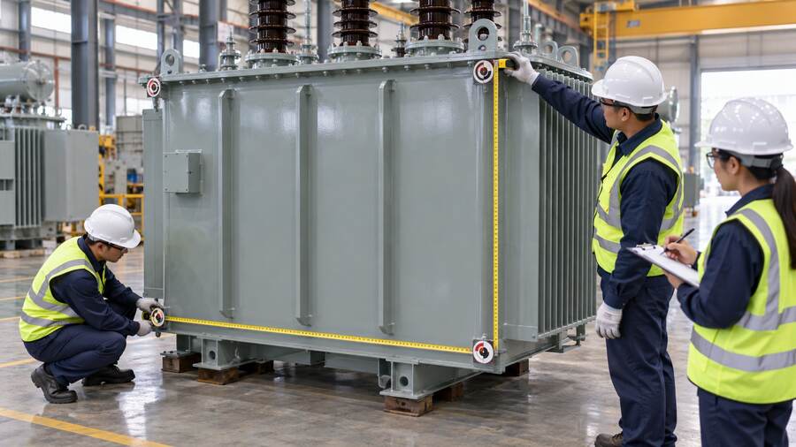
AI-generated engineering illustration of transformer tank dimensional checks.
A dimensional matrix converts drawings into measurable checkpoints. It should state the design reference, nominal dimension, permitted tolerance, measurement method, responsible party and evidence required. Keep the matrix revision-controlled and link it to the drawing register. When a drawing changes, the affected checkpoints should be reassessed rather than copied forward automatically.
Interface | Dimension or condition to verify | Why it matters | Risk if incorrect |
|---|---|---|---|
Foundation | Base length and width, support centers, anchor pattern, rail or wheel gauge | Controls equipment seating and load transfer | Site drilling, shimming or foundation rework |
HV connection | Bushing centerline, terminal height, phase spacing and orientation | Controls conductor geometry and electrical clearance | Buswork redesign or unsafe mechanical loading |
LV connection | Cable-box size, gland-plate position, busduct flange and access | Coordinates cables, busduct and installation tools | Forced alignment, poor bend radius or delayed termination |
Cooling system | Radiator projection, fan access, valve clearance and removal space | Protects airflow and maintenance access | Blocked cooling or inability to service components |
Transport | Shipping length, width, height, mass, center of gravity and lifting points | Defines route, trailer and crane requirements | Permit failure, unsafe lift or route obstruction |
Accessories | Control cabinet, marshalling box, conservator, pipework and monitor locations | Coordinates walkways and field wiring | Access conflict or cable extension work |
One overall dimension is rarely enough. The operating envelope includes fully assembled radiators, conservator, bushings and local cabinets. The shipping envelope may exclude detachable items and include temporary packing frames. The maintenance envelope covers radiator removal, bushing handling, filter connections, fan replacement and access for test equipment. All three should be shown because a layout that accepts the operating footprint can still block assembly or future maintenance.
Before the inspection, compile the approved general arrangement, foundation plan, terminal arrangement, transport drawing, packing list and relevant interface sketches. Record each revision. Redline comments and email instructions should not be used as the measurement basis unless they have been formally incorporated into an approved document. This prevents the inspection team from comparing physical equipment with an obsolete drawing.
The drawing review should be coordinated with the distribution-project transformer selection process, because voltage class, insulation arrangement and connection method can change the equipment envelope. The civil designer also needs final equipment mass, support reactions and oil containment information, not only length and width.
Dimensions are only repeatable when they are taken from agreed datums. The inspection procedure should identify a primary longitudinal datum, a transverse centerline and a reference elevation. Measurements taken from tank edges can be misleading where welded surfaces, stiffeners or removable panels vary. Foundation and terminal dimensions should be related to fixed support centers or drawing datums.
Tools must suit the required accuracy and distance. Steel tapes may be adequate for an overall shipping envelope, while terminal centers and flange patterns may require calibrated rules, levels, laser equipment or templates. The record should identify the tool and calibration status where required by the quality plan. Photographs should show the start and end points, not merely a tape placed near the equipment.
Example only — replace values and tolerances with approved project data.
Checkpoint | Drawing value | Permitted tolerance | Measured result | Disposition |
|---|---|---|---|---|
Base support center | Project value | Contract value | Recorded at inspection | Accept or raise deviation |
HV phase center spacing | Project value | Contract value | Recorded at inspection | Accept or raise deviation |
LV cable-box center height | Project value | Contract value | Recorded at inspection | Accept or raise deviation |
Maximum shipping height | Route limit | Transport allowance | Packed configuration | Release or revise packing |
Foundation mismatches are among the most disruptive because corrective work may involve concrete, embedded plates or rails. Verify the number and position of support points, base channels, wheel orientation, jacking pads, anchoring holes and pull points. If the transformer uses wheels, confirm whether they are installed for longitudinal or transverse movement and whether the rail gauge matches the civil drawing.
Measure the clear space required to operate jacks and install anchors. A base can fit the foundation while leaving no safe access for tools. Confirm earthing pad positions and bonding routes at the same time. The equipment layout should also remain compatible with the selected oil-immersed transformer configuration and the project oil containment arrangement.
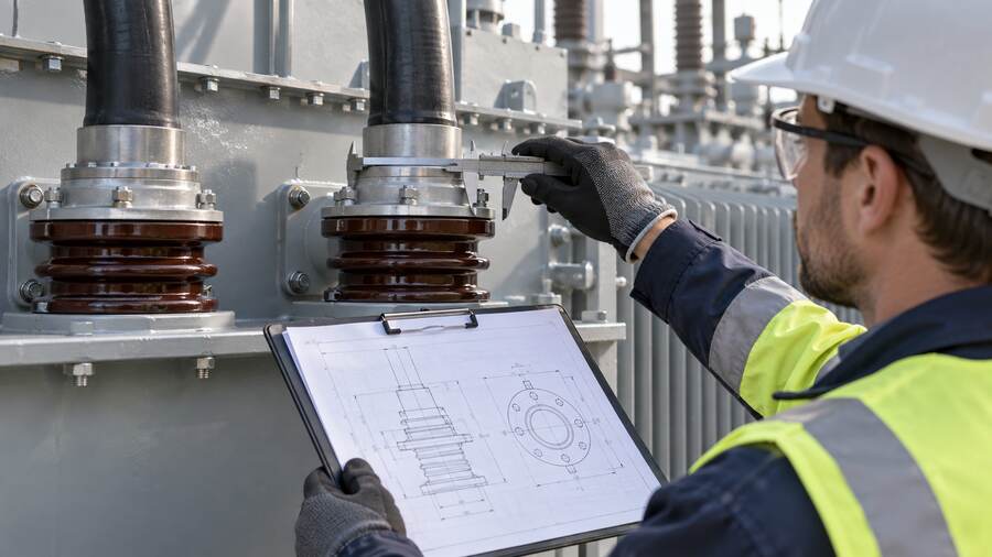
AI-generated engineering illustration of a transformer bushing interface check.
Connection interfaces require both dimensional and orientation checks. For bushings, verify phase sequence, center spacing, terminal height, inclination and reference direction. Check the distance from nearby metalwork and the space required for connectors. Do not infer electrical clearance acceptance from a single tape measurement; the approved insulation coordination and layout documents remain the governing basis.
For cable boxes, confirm entry direction, gland-plate size, removable panels, internal termination space and access to fasteners. Cable bending radius and support loads belong to the cable-system design, but the transformer drawing must provide a workable termination envelope. For busduct, inspect flange size, bolt pattern, centerline and flexible connection allowance. Forced alignment can transfer unacceptable loads into transformer terminals.
High-voltage units such as a 132kV–138kV power transformer may have tall and widely spaced external interfaces. The transport and erection plan should show which items are removed for shipment and how final alignment will be verified after assembly.
Radiators, fans, pumps, valves and pipework can extend beyond the tank outline. Verify the fully assembled projection and the space needed to open valves, remove fan guards and access cooler connections. Compare radiator orientation with walls, barriers and adjacent equipment. A dimensional pass is not useful if airflow is restricted by a civil feature added after design approval.
Control and marshalling cabinets should open fully without obstructing walkways. Check door swing, cable entry and working space. Confirm that temperature indicators, oil-level devices, sampling points and filter connections can be reached safely. These practical checks reduce site modifications and support future maintenance.
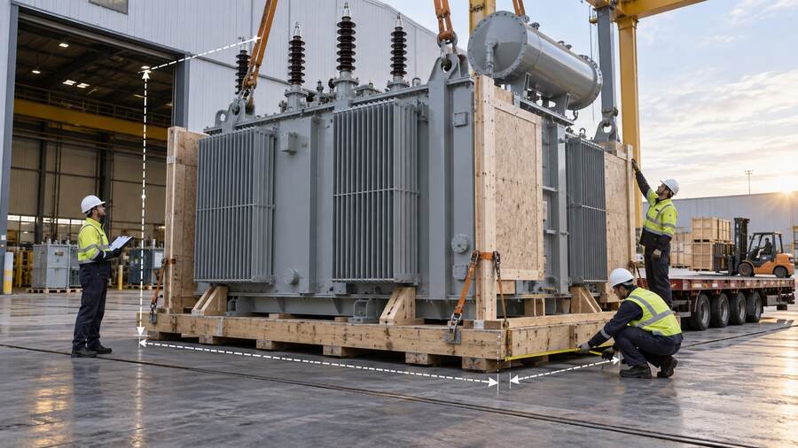
AI-generated engineering illustration of a packed transformer transport-envelope inspection.
The unit released for transport may differ significantly from the operating arrangement. Verify the packed base footprint, overall height, center of gravity marking, lifting and lashing points, detachable-item list and package sequence. Dimensions should include protective covers, timber frames and temporary bracing. A route study based on the bare transformer can be invalidated by packing.
Compare the measured envelope with trailer drawings, gate openings, road restrictions and crane capacity. Record the configuration in photographs. If radiators, bushings or conservator components ship separately, identify package numbers and preservation requirements. The packing list should match the erection sequence so critical parts can be found without unnecessary unpacking.
A failed checkpoint should not be hidden by changing the inspection record. Raise a deviation or nonconformance against the approved requirement, assess impact across disciplines and obtain authorized disposition. Some deviations can be accepted after engineering review; others require rework or revised site design. The decision should identify affected drawings and responsibilities.
Dimensional closure should be integrated with FAT and thermal evidence such as the transformer temperature-rise test review. Shipment release should require an approved dimensional report, closed deviations, final drawings and an aligned packing list. Electrical test completion alone does not prove mechanical interface readiness.
Approved general arrangement and interface drawings are listed by revision.
Foundation centers, supports, anchors, rails and jacking points are measured.
HV and LV terminal locations, orientation and access are verified.
Radiator, cabinet, valve and maintenance envelopes are checked.
Operating and packed transport dimensions are recorded separately.
Measurement tools and evidence satisfy the inspection plan.
Deviations are formally assessed and closed or approved.
Final drawings and packing documents reflect the inspected configuration.
The dimensional report should be usable by people who were not present at the factory. Give every checkpoint a drawing reference, datum, measured value, tolerance and photograph number. Mark detachable components clearly and state whether a result represents the assembled or shipping condition. Where a laser survey produces a point cloud or electronic file, retain a readable summary in the manufacturing record rather than relying on proprietary software alone.
The EPC contractor should compare the report with the latest civil and electrical models before issuing shipment release. This review is especially important when site construction has continued during manufacturing. A foundation change, revised cable trench or altered busduct route may create a conflict even when the equipment matches the approved supplier drawing. Document the comparison and identify who has authority to accept a variance.
Site receipt inspection should reuse the factory datums. Check the packed unit for movement or damage, then confirm critical dimensions after assembly. Do not treat the factory record as proof that transport and erection preserved alignment. Bushing supports, cable boxes, radiators and local cabinets may need a final position check before connections are made. Closing this loop gives the project a traceable line from approved drawing to factory measurement and installed equipment.
A disciplined transformer dimensional inspection prevents avoidable foundation rework, connection conflicts and transport delays. Zisheng Electric can review project transformer requirements together with the civil, electrical and logistics interfaces needed for inspection planning.
For review, provide the transformer data sheet, drawings, load list, technical specification, single-line diagram, grid parameters, environmental conditions, foundation plan, cable or busduct details and installation-site restrictions. Suitable equipment may include oil-immersed distribution transformers and high-voltage power transformers configured to the approved project requirements. Contact Zisheng Electric through the engineering inquiry page. “Our engineering team will review the requirements and respond to project inquiries within 24 hours.”