Please Choose Your Language
Views: 0 Author: Zisheng Electric Technical Engineer Publish Time: 2026-09-07 Origin: Site
Zisheng Electric treats dielectric testing as a controlled engineering activity, not a final-minute voltage application. A transformer applied voltage test checks whether the insulation between each winding and earth, and between windings where applicable, can withstand the specified power-frequency test voltage. The result supports factory release, but only when the test level, connections, duration, measuring system and acceptance criteria are agreed before the factory acceptance test (FAT).
This distinction matters to EPC contractors and project owners. A transformer can have correct ratio, resistance and losses yet still have an insulation weakness caused by contamination, inadequate clearance, damaged leads, assembly error or moisture. Conversely, an incorrectly arranged test can overstress components that were not intended to receive the applied voltage. The purchase specification and inspection plan should therefore define exactly what is being proved and what evidence must be handed over.
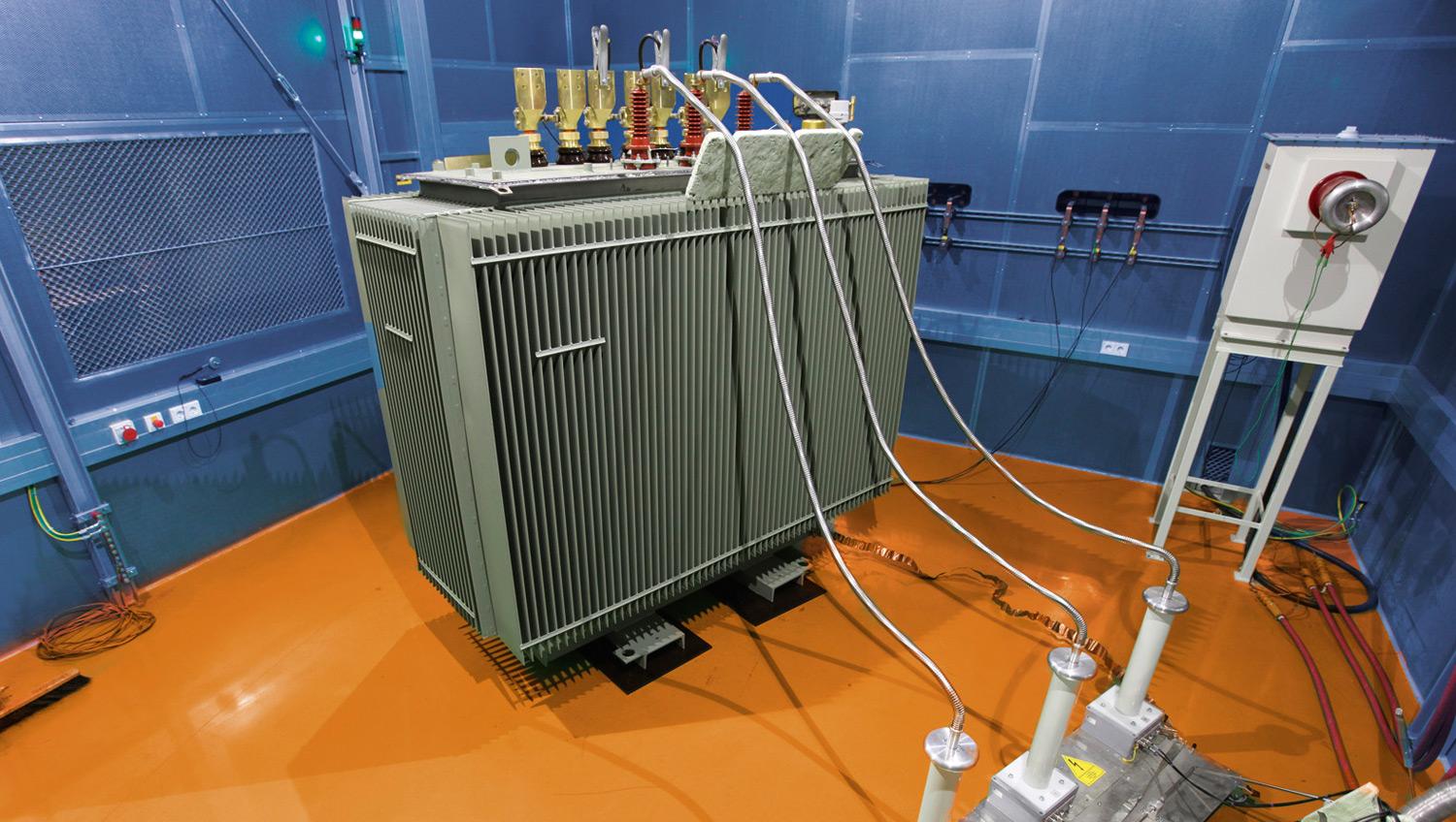
During the test, the winding under test is normally connected together at its terminals and energized from a suitable test source. Other windings, the core, tank and specified metallic parts are connected to earth according to the approved procedure. This creates electrical stress mainly across the insulation from the tested winding to earth and to the other grounded windings.
The test is different from an induced-voltage test. Applied voltage primarily examines major insulation to earth, while induced testing uses transformer action to stress turn-to-turn, phase-to-phase and other longitudinal insulation. The two tests answer different questions and should not be substituted for one another. The project test schedule must identify which tests apply to each winding and whether partial-discharge measurement is separately required.
IEC 60076-3 specifies transformer insulation requirements, corresponding insulation tests, minimum dielectric test levels and external clearances. The contract should state the applicable edition and any utility amendments. Zisheng Electric does not recommend copying a voltage from another project: the correct value depends on the highest voltage for equipment, winding connection, insulation level, neutral design and specification.
The approved datasheet should show the rated winding voltages, highest voltage for equipment, lightning impulse withstand level where required, power-frequency withstand level, neutral insulation and whether insulation is uniform or graded. These fields affect design clearances, lead routing, bushings and test connections. If the schedule is incomplete, the factory may prepare a test that does not match the owner's coordination study.
Neutral terminals need particular attention. A fully insulated neutral and a reduced-insulation neutral do not have the same test duty. Autotransformers, regulating windings, tertiary windings and accessible stabilizing windings also require project-specific connection diagrams. The FAT procedure should contain a simple marked drawing rather than relying on text alone.
| Specification item | Why it matters | Risk if incorrect | FAT check |
|---|---|---|---|
| Highest voltage for equipment | Sets the insulation coordination basis | Wrong dielectric level or inadequate clearance | Match approved datasheet and nameplate |
| Winding and neutral insulation | Defines the portions stressed to earth | Unintended neutral or lead overstress | Review winding diagram and grounding points |
| Applied test voltage and duration | Defines the contractual withstand duty | Invalid test or excessive stress | Record actual voltage, time and waveform |
| Tested and grounded terminals | Controls the electric field during the test | Unrepresentative insulation stress | Photograph and sign the connection diagram |
| Accessories connected or isolated | Protects devices with different ratings | Damage to surge arresters, electronics or CT circuits | Use an approved isolation checklist |
| Measuring and protection system | Confirms accuracy and safe interruption | Unreliable evidence or prolonged fault energy | Verify calibration and trip settings |
The transformer should be in the assembly and oil condition specified by the procedure. Bushings, tap changer position, temporary links and earthing must be documented. Oil-filled equipment should have completed the agreed oil processing and settling period. Surface contamination around bushings and temporary test leads can cause external flashover that does not represent internal insulation condition.
Inspect the tank earth, core-earth arrangement, bushing condition and clearances around energized terminals. Remove or isolate devices that cannot withstand the test only when the approved procedure requires it, and record every disconnection. Surge arresters, low-voltage electronics, monitoring modules, fan controls and secondary wiring must never be handled by assumption.
Dielectric tests belong in a coordinated FAT sequence. Preliminary ratio, vector group, winding resistance and insulation checks help identify assembly errors before high voltage is applied. Post-test checks can demonstrate that no unexpected change occurred. The sequence should also consider oil sampling, induced-voltage testing and any partial-discharge measurement so that preparation is not repeatedly disturbed.
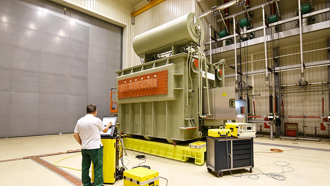
The test set must be suitable for the required voltage and capacitive load. The measuring chain should have current calibration traceable under the project's quality system. The report should identify the test transformer, divider or measuring device, serial numbers, calibration validity, voltage range and protective settings. A handwritten statement that the transformer “passed hipot” is not adequate FAT evidence.
Raise the voltage in a controlled manner, stabilize it at the specified level, maintain it for the required duration and reduce it safely. The operator should watch for protective trips, abnormal current, discharge, smoke, noise or external flashover. Personnel exclusion zones, barriers, warning lamps, interlocks and discharge/earthing procedures are part of the test, even though they are not SEO-visible deliverables.
Acceptance is normally based on completing the specified duty without insulation breakdown or other disqualifying behavior defined by the standard and contract. Do not invent a leakage-current limit unless the project procedure establishes one. Recorded current can help identify an abnormal event, but transformer capacitance, test equipment and connection arrangement influence the value.
If a trip or discharge occurs, stop and preserve the evidence. Do not immediately repeat the test at full voltage. Record the voltage and elapsed time, inspect bushings and leads, check environmental and surface conditions, review the protection indication and consult the approved nonconformance process. An external flashover caused by inadequate temporary clearance requires a different response from suspected internal breakdown.
Further work may include insulation resistance, capacitance and dissipation-factor measurements, oil tests, inspection of accessible connections or other agreed diagnostics. The engineering team should decide whether a repeat test is justified and under what conditions. Repetition without a documented cause can add insulation stress while hiding the original event.
Hypothetical example—values must be completed from the approved project insulation schedule:
Test: Perform the transformer applied voltage test for each applicable winding in accordance with the contract-specified edition of IEC 60076-3 and the approved FAT procedure. Connections: Provide a marked terminal diagram showing the energized winding, shorted terminals, grounded windings, tank/core earths and isolated accessories. Test duty: Apply [project value] kV at power frequency for [project duration] seconds. Evidence: Submit calibrated instrument details, actual voltage/time record, connection photographs, operator and witness signatures, observations and nonconformance disposition where applicable. Restoration: Complete and sign a post-test reconnection checklist before subsequent functional tests or dispatch.
Applied voltage evidence should sit within a coherent manufacturing record. Compare the transformer identification across the nameplate, approved drawing, test sheet and calibration attachments. The same tap designation and terminal names should be used throughout. Zisheng Electric's guides to ratio and vector group testing, winding resistance testing, no-load loss testing and IEC 60076 design and manufacture provide related review points.
The record should also state whether the FAT result is a routine test certificate, a purchaser-witnessed activity or part of a wider special-test program. Witness attendance does not transfer responsibility for safe execution or technical correctness. Hold-point release should refer to the accepted report and any closed punch items.
Insulation coordination should be established before ordering, not added at FAT. System voltage, grounding, overvoltage protection, altitude, pollution, bushing clearances and neutral duty influence the transformer specification. Zisheng Electric can review these requirements for oil-immersed transformers, including a 110 kV oil-immersed transformer and the S11 10–35 kV distribution transformer. Final ratings and test levels must be confirmed against the approved project data.
A signed result is not enough if the report cannot be traced to the approved insulation schedule. The reviewer should find the transformer serial number, equipment tag, winding designation, rated voltage, tap position, selected test voltage, frequency, duration and connection sketch in one controlled record. Instrument make, model, identification number, range and calibration expiry should also be visible. Where the test set uses a divider or measuring transformer, the recorded ratio and the point from which voltage was measured need to be unambiguous.
Compare the report with the witnessed configuration rather than relying on a generic template. Terminal labels should match the nameplate and drawings. Any temporarily disconnected surge arrester, neutral device, bushing CT circuit or monitoring accessory should appear on the isolation-and-restoration sheet. If environmental conditions, audible discharge, test-set instability or an external flashover affected the sequence, record the event and its disposition instead of deleting the interrupted run.
The purchaser should also define the release logic. A satisfactory applied-voltage result does not automatically close unrelated punch items, while a clerical error should not be treated as an insulation failure. Classify each finding, assign an owner and due date, and require technical acceptance of revised evidence. Before shipment, verify that the approved report, calibration certificates, connection diagram, photographs allowed by the test-area rules and signed restoration checklist are included in the manufacturing dossier. This document-level review turns the test from a momentary factory activity into usable evidence for installation, energization and any later condition investigation.
A useful transformer applied voltage test is traceable from the insulation schedule to the physical connection and the signed result. It explains why the selected voltage applies, what was grounded, what was isolated, how the duty was measured and how the transformer was restored. That level of control reduces the risk of an invalid test, an avoidable accessory failure or an unresolved event delaying shipment.
Send Zisheng Electric the single-line diagram, transformer datasheet, insulation coordination schedule, winding diagram, bushing arrangement, neutral-earthing details, FAT specification and utility requirements. Our engineering team will review the requirements and respond to project inquiries within 24 hours.