Transformer fiber optic winding temperature monitoring can give an owner direct temperature readings from selected locations inside the active part. The procurement challenge is to make those readings meaningful: each displayed channel must connect to a documented probe location, an intact optical path and an agreed operating function. Buying a monitor with enough channels does not, by itself, establish that chain.
This guide is for buyers, transformer designers and EPC engineers defining a new transformer package. It concentrates on measurement coverage, factory evidence and control interfaces. Probe installation inside a winding belongs in the manufacturer's approved design and manufacturing process; it is not an accessory to add casually after the transformer is assembled.
Start by deciding what the owner expects to do with the data. Possible purposes include reviewing thermal performance during an agreed factory test, monitoring selected winding locations in service, trending unusual temperature differences, or providing inputs to an approved cooling and alarm scheme. Each purpose needs a different evidence boundary. A trend-only channel should not quietly become a protective trip input during commissioning.
Record the required measured quantities, the devices that will receive them and the people responsible for interpreting them. State whether the scope includes a local display, archived data, remote communications, analogue outputs or relay contacts. Specify these as functions first, then ask the supplier to identify a compatible probe, feedthrough and monitor arrangement.
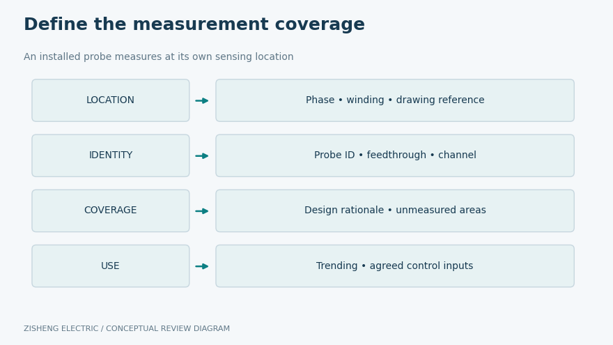
A probe measures temperature at its sensing location. The highest reading among installed probes is the highest measured value in that group; it is not automatic proof of the highest temperature anywhere in the transformer. The design team should explain how the proposed locations relate to predicted thermal behavior and what important areas remain unmeasured.
The Neoptix T/Guard Link description illustrates a commercial system intended for direct winding temperature monitoring with compatible optical probes. Use that as an example of the measurement approach, not as evidence that every offered transformer includes it or that all probes and monitors can be mixed.
A channel schedule should explain where the measurement comes from and what it represents.
Ask for a location schedule linked to the winding drawings. Each entry should identify the transformer, phase, winding, physical location reference, probe identifier and intended monitor channel. Where the exact internal design is confidential, agree a controlled location description that still lets the purchaser understand coverage and interpret the results. An anonymous list of channel numbers is insufficient.
Probe quantity should follow the engineering objective. More channels can increase observed coverage, but their value depends on placement, routing, installation quality and the way results will be used. Request the designer's rationale for the proposed locations and any spare probes. Avoid selecting a quantity solely because a catalogue monitor has an attractive channel count.
Record design changes that affect the schedule. A moved probe, changed lead route or substituted feedthrough can alter the final arrangement without changing the headline specification. The approved drawing, manufacturing record and as-built channel list should converge before release. Otherwise the owner may receive precise readings attached to the wrong winding labels.
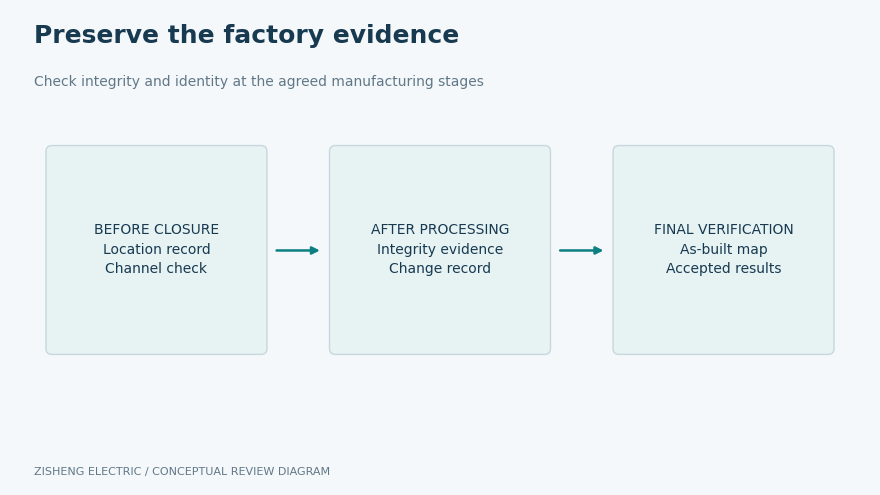
Identify the stages at which probes become inaccessible. Agree which checks and photographs are needed before those stages, and who reviews the records. These hold points should support the manufacturer's process rather than interrupt it with an unplanned handling operation. Any inspection requiring access inside the active part needs advance coordination with the factory.
Review the sensor, internal lead, tank feedthrough, external extension and monitor input as one chain. Confirm compatibility through the responsible suppliers, including connector types and any permitted extension arrangements. The tank penetration also belongs to the transformer's mechanical and sealing design. A working optical signal does not demonstrate an acceptable oil boundary.
The Qualitrol T2 probe description identifies an oil-permeable optical sensor intended for oil-filled transformers and manufacturing exposure. That is a product-specific description. Obtain the current installation and process limits for the exact offered model rather than transferring claims between different sensor families.
Ask the factory to control routing, support, identification and protection during assembly. Bend limits, allowable pulling forces, connector treatment and process exposure must come from the actual supplier instructions. Do not put a generic bend radius or a cleaning method in the purchase specification without checking that it applies to the selected system.
Review item | Evidence requested | Decision to record |
|---|---|---|
Measurement purpose | Monitoring and control function list | Which functions may use each channel |
Thermal coverage | Location schedule and design rationale | What the installed probes can demonstrate |
Optical compatibility | Probe, extension, feedthrough and monitor schedule | Approval of the complete measurement chain |
Manufacturing survival | Stage checks linked to assembly records | Whether channel integrity remains acceptable |
Remote signals | Channel map, units, validity and update behavior | Whether the receiving system interprets data correctly |
Handover | As-built locations, settings and original records | Whether future maintenance can trace each reading |
Give every open item an owner and a required decision date. Distinguish an unresolved design question from a completed inspection with a documented exception. A single green status against the entire monitoring package can conceal an unverified channel or a missing control-system interface.
Keep the stage records that connect embedded locations to the final channel map.
The inspection plan should identify appropriate integrity checks before and after relevant manufacturing stages. Retain the actual results and the equipment references used. The objective is to detect a change while the factory still has an approved opportunity to investigate it. A final screen showing plausible temperatures cannot explain when a channel became unavailable.
At each agreed stage, reconcile the probe identifier, physical location and monitor channel. Where extensions are disconnected for processing or shipping, preserve the connection map and labels. A channel swap can produce believable values while undermining phase comparisons and alarm attribution. The quality record needs to demonstrate identity as well as signal availability.
Define the acceptance method for measurement performance with the supplier. This may include appropriate reference checks and equipment records under an agreed procedure. Do not assume that an ambient comparison alone proves accuracy throughout the service range. Equally, do not demand a test that exposes an embedded probe or the insulation system to an unapproved condition.
If optical data are collected during a temperature-rise test, preserve the load, cooling state, relevant electrical conditions, timestamps and test references alongside the readings. Identify how those observations relate to the agreed test scope. They add local information; they do not automatically replace other required temperature determinations or establish an unrestricted loading capability.
Keep raw channel data where the package requires it, not only a screenshot of the final maximum. Mark unavailable channels and gaps visibly. If a correction or relabeling is made, retain the original record and the approved explanation so that later reviewers can reproduce the conclusion.
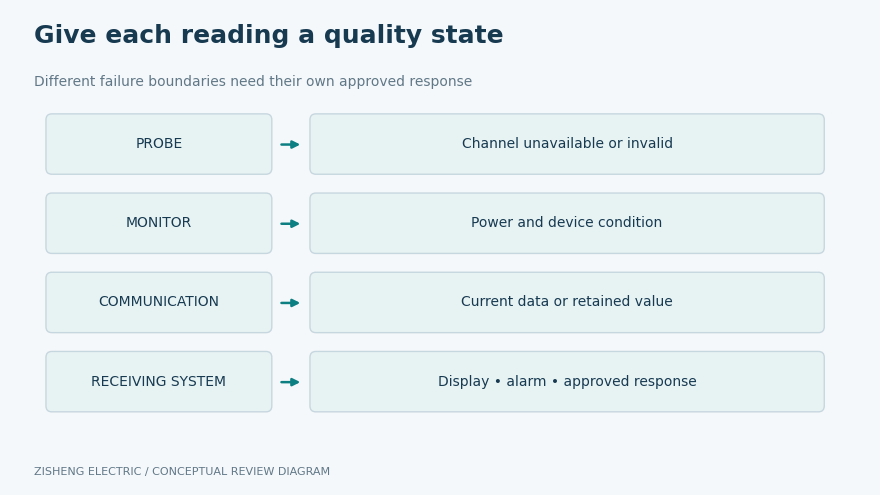
A numeric value needs context. The interface schedule should state engineering units, scaling where applicable, channel names, update behavior and the indication used when a measurement is unavailable. The receiving system must be able to distinguish a current valid reading from an old retained value. Define that distinction in the functional specification before software integration.
Discuss loss of a probe, loss of monitor power and loss of communications separately. These events do not necessarily have the same consequence. The approved design must determine whether each event creates an alarm, affects an automatic function or calls for an operating restriction. The article does not prescribe a universal trip response for unidentified equipment.
Where the monitor contributes to cooling control or protection, allocate responsibility for settings and fallback behavior. The transformer designer provides the relevant thermal basis; the control and protection engineers approve how measurements are used. Verify the complete function within the authorized test boundary, including the actual receiving device and configured logic.
Specify how the receiving system recognizes unavailable or outdated temperature information.
External extensions, connectors and the monitor may have service arrangements that differ from embedded sensors. Ask which components can be inspected or replaced under the approved maintenance procedure, and which actions would require transformer intervention. Do not describe an inaccessible winding probe as a routine field-replaceable spare merely because the external monitor is replaceable.
Specify practical identification at external connection points and a protected location for the channel map. Include environmental requirements for the monitor cabinet, auxiliary supply, cable protection and access. These details determine whether technicians can diagnose a missing reading without confusing optical-channel faults with power or communications problems.
Preserve a configuration backup and a readable settings record appropriate to the actual device. Record firmware and model details where they affect interpretation or replacement. Supplier support arrangements should explain how the owner obtains compatible components and the instructions needed to restore the accepted configuration.
Imagine that one offer includes six embedded probes and a local monitor, while another includes twelve probes, remote data and additional alarm contacts. This is an illustrative comparison, not a recommendation for either quantity. Ask both suppliers to complete the same location and function schedule. Only then can the purchaser see whether the difference concerns thermal coverage, available channels, external interfaces or documentation.
Check the scope exclusions as carefully as the included equipment. One offer may leave external extensions, cabinet installation or control-system mapping to the EPC contractor. Another may include those items but provide only preliminary probe locations. Record the remaining engineering work and its owner so that the commercial comparison reflects a complete, usable measurement package.
Before purchase, agree the point at which the proposed arrangement becomes a committed design. The bid-stage schedule can remain provisional where necessary, but the contract should identify the final drawing review and verification evidence. This protects both parties from treating an early concept as an undocumented guarantee.
The EPC power solutions review provides a place to coordinate transformer, control and documentation responsibilities. The core lamination quality guide addresses a separate manufacturing evidence topic; its records should remain distinct from proof of the optical measurement chain.
Initial equipment discussions can reference the S11 oil-immersed transformer and SZ11 transformer range. Optical monitoring must be confirmed in the project-specific offer. It is not implied by either product name, and its suitability depends on the design, duty and agreed accessory scope.
Send the transformer ratings, load profile, cooling requirements, intended monitoring purpose, preferred interface methods and document schedule. Identify whether the owner wants local trending, remote data, cooling inputs or another approved function. Ask the supplier to propose a location schedule, complete system configuration, factory verification plan and service documentation.
Acceptance is strongest when a reviewer can trace any displayed channel back to its approved location and forward to its intended use. Close exceptions with an agreed disposition, and retain the records that explain coverage and limitations. Transformer fiber optic winding temperature monitoring then becomes a usable engineering tool rather than an unexplained collection of temperatures. Share the scope with Zisheng Electric for a project-specific design and quotation review.