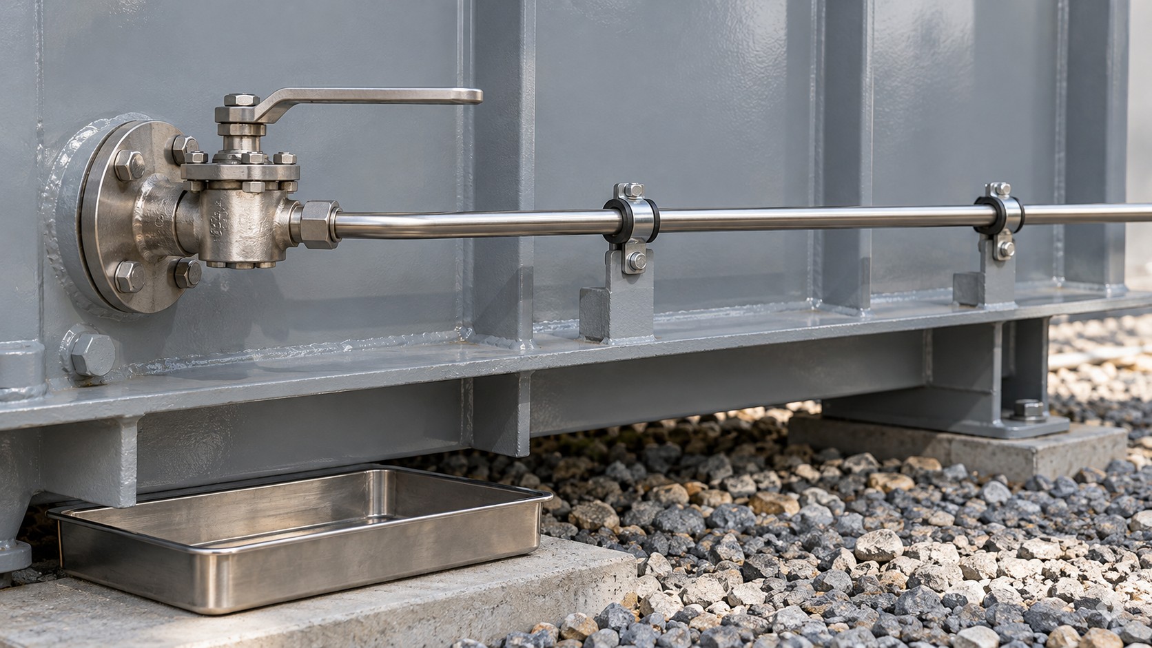
Zisheng Electric treats a transformer online DGA monitor interface as a small oil system with its own mechanical, electrical and information boundaries. Buying a gas analyzer does not establish how representative oil reaches it, how that oil returns to the transformer, or how an operator distinguishes an equipment alarm from an unreliable measurement. Those questions belong in the transformer purchase specification before valve positions and cabinet supports are frozen.
This guide helps EPC engineers and equipment buyers define those boundaries for a new oil-immersed transformer. It focuses on the external sampling circuit, installation arrangement and acceptance evidence. It does not prescribe gas alarm limits, diagnose an internal fault or replace the selected monitor manufacturer's installation instructions. A single-port sensor and a pumped, multi-gas analyzer may require very different interfaces; their connection drawings should never be treated as interchangeable.
State which oil compartment is being monitored. Main-tank oil, a separate tap-changer compartment and another independent fluid circuit have different identities and histories. Record the transformer identifier, compartment identifier, fluid type, monitor type and sampling arrangement on the same schedule. An instrument that reports plausible numbers against the wrong equipment tag can create more confusion than an obvious communication failure.
The first drawing should show the complete route from the transformer connection through isolation valves, tubing, monitor and return connection, where a return is required. Include the component owner at each break in scope. A monitor supplier may provide fittings at the cabinet but exclude the transformer valve adapter, supporting brackets or site-installed tubing. Discovering that exclusion after delivery can lead to improvised connections and unclear responsibility for leaks.
List the gases and other quantities required by the owner's monitoring strategy, then ask the selected supplier for the conditions under which its stated performance applies. Keep this instrument-performance review separate from the physical installation review. Neither a successful communications demonstration nor an analyzer certificate proves that the completed oil circuit is clean, correctly connected and suitable for the operating conditions.
For the broader signal architecture, use the interfaces described in our transformer digital monitoring specification guide. The present review should add the oil-circuit detail that a general sensor list cannot capture.
Ask both manufacturers to approve the proposed connection positions. Check the relevant oil levels, compartment boundary, local flow conditions, access and the monitor's permitted elevation and pipe route. A conveniently located valve is not automatically an acceptable analyzer connection. A drawing marked only “DGA provision” leaves too much open for a factory inspector to verify.
As a product-specific example, Vaisala's OPT100 installation instructions require both transformer oil connections to remain below oil level and warn that its initialization involves flow in both directions. These details demonstrate why the selected equipment manual matters. They are not universal dimensions or operating rules for every online DGA system.
Where the transformer is ordered before the monitor is selected, define a documented reservation boundary. State which valves, support provisions and space envelopes are included, what remains provisional, and the latest date for closing the interface. Avoid presenting an unreviewed connection pair as compatible with all future analyzers.
Consider how a laboratory sample will be obtained after the monitor is installed. A new enclosure or tube route should not obstruct the approved sampling location or force maintenance staff to disturb the online circuit whenever an independent sample is needed. Review this access alongside our oil sampling point design guidance. Record which sampling activity is permitted at each connection and who approves any shared arrangement.
The schedule below is a procurement and inspection aid. Populate it with the offered equipment documents rather than treating it as a set of standard values. Each unresolved row should have an owner and a closure date, so missing information cannot silently become a contractor assumption.
Interface item | Decision to close | Evidence required | Consequence if left open |
|---|---|---|---|
Oil compartment | Identify exactly which fluid volume is monitored | Approved compartment and connection drawing | Data may be assigned to the wrong asset or fluid circuit |
Intake and return | Confirm locations and operating oil-level envelope | Monitor supplier review of transformer arrangement | Unrepresentative sampling or an unsuitable hydraulic path |
Tube route | Agree material, fittings, supports and thermal movement | Installation layout and selected supplier instructions | Leak exposure, vibration damage or blocked access |
Cabinet mounting | Choose support, clearance and environmental protection | Mounting drawing and maintenance envelope | Service tasks become difficult or equipment is exposed beyond its rating |
Power and earthing | Assign supply, protection and connection ownership | Electrical schedule and termination drawing | Commissioning delay or uncontrolled installation changes |
Data quality | Define stale data, monitor fault and measurement status | Point list and functional test cases | Old or invalid values may be interpreted as current measurements |
Handover baseline | Record configuration and initial operating context | As-left settings and time-stamped commissioning record | Later trends cannot be interpreted against a reliable starting point |
Review connection ownership, tube supports and service clearance before installation.
A pipe route must accommodate actual construction tolerances. Identify the relative movement between the tank, independent cabinet foundation and supporting steel. Ask the responsible designer to select an appropriate arrangement rather than pulling rigid tubing into alignment during installation. Where flexible sections are proposed, require confirmation of fluid compatibility, pressure and temperature capability, bend limits and the intended replacement method.
Show supports and service access on the drawing. Tubing should not become a handhold, a step or an obstacle to removing another accessory. Review nearby fan guards, radiator valves, lifting points and access doors. An arrangement that looks clear in elevation can still block a technician's working position when the cabinet door is open.
The selected manufacturer's cleaning and assembly method should control how tubing and fittings are prepared. Vaisala's published instructions, for example, emphasize clean, dry components and protection against contamination. The project should translate the applicable requirements into receiving and installation checks without inventing a substitute procedure. Keep connection ends protected until the approved assembly activity begins.
Keep fittings protected and verify the selected supplier assembly requirements.
The owner needs a documented way to identify the normal operating configuration and recognize when the monitor has been isolated for maintenance. Use durable component identities that match the as-built oil-circuit drawing. The maintenance record should identify what was isolated, what was disturbed, who checked restoration and which commissioning checks were repeated. This is an information requirement, not a universal valve-operating sequence.
Review ambient temperature, direct sunlight, rainfall, flooding exposure, dust, salt contamination and access restrictions for the exact installation position. A transformer may be suitable for the site while a separately selected analyzer requires a different enclosure, weather shield or mounting location. Confirm those requirements against the monitor's current documentation and the project environmental specification.
Allow space for opening doors, removing service modules and connecting the required tools. A person should not need to lean across hot piping or enter an unauthorized electrical area simply to read a nameplate. Record the approach route and working position during design review, then check them during the site walkdown. Maintenance clearance is useful only when it survives the final cable trays, fencing and other site equipment.
For cold conditions or fluids with different viscosity characteristics, obtain the supplier's installation provisions rather than selecting trace heating from habit. For hot locations, account for solar exposure and the cabinet's own heat dissipation. These choices affect the external analyzer installation and should not be confused with the transformer's thermal rating.
Distinguish valid measurements, stale values and monitor fault states in the operator display.
Specify the destination of each value and the meaning of each status point. The control system should distinguish a measured gas value from a monitor fault, an initialization state, a communication interruption and data that have not been refreshed. Confirm units, update behavior, timestamps and asset naming with the integrator before testing begins.
Alarm thresholds and response actions belong to the owner's approved condition-monitoring strategy. A monitor alarm should not be connected to a transformer trip function merely because a spare contact is available. Any protective action requires its own approved engineering basis, coordination and testing. Keep the condition-assessment workflow visible in the point list so operators know who reviews an abnormal trend.
Retain the configuration version and access responsibilities. The handover package should explain who can change settings, how approved changes are recorded and how the current configuration is backed up. Remote support arrangements must follow the owner's access policy. A permanent vendor connection is not an implied requirement of online monitoring.
Factory inspection can confirm supplied valves, connection identities, mounting provisions, cable interfaces and drawings. It can also verify the monitor assembly if that equipment is within factory scope. State explicitly whether the analyzer is installed, separately packed or supplied later by another contractor. The FAT report should not imply that a site-installed oil loop has already been accepted.
Site acceptance must address the completed arrangement: actual pipe route, supports, connection integrity, access, power, earthing and data mapping. Use the selected manufacturer's commissioning instructions and the project's approved inspection plan. Record any differences from the factory configuration and obtain the appropriate approvals before treating the system as ready for normal service.
A screen displaying numbers is an incomplete demonstration. Include approved tests for loss of communications, instrument fault indication and restoration of valid data. Compare the expected status at the monitor, gateway and operator display. Preserve the test conditions and actual responses, rather than accepting a screenshot with no description of how it was produced.
Where a laboratory comparison is required, agree the sampling timing, fluid compartment, laboratory method and interpretation responsibility in advance. Values from different times or methods should not be forced to match an arbitrary tolerance. Preserve load, temperature and recent oil-handling context so the responsible specialist can judge whether a difference warrants investigation.
The final dossier should join the as-built oil-circuit drawing, monitor identity, transformer serial number, electrical terminations, communications point list and configuration record. Add installation checks, supplier commissioning records, outstanding-item closure and the initial trend period agreed with the owner. Keep raw records accessible rather than relying entirely on a presentation or a summary dashboard.
Define the response route for a failed monitor as well as an abnormal transformer indication. Operations may need temporary laboratory sampling, supplier support or further engineering review, depending on the approved strategy. Naming the responsible party and necessary evidence at handover makes that decision faster without pretending that a monitoring device can guarantee the absence of faults.
For new oil-immersed transformers and projects considering our 110kV and 115kV power transformer range, define the transformer online DGA monitor interface while the mechanical arrangement is still open for coordination. Product voltage alone does not determine the correct analyzer or connection layout.
Send Zisheng Electric your drawings, data sheets, load list, technical specification, single-line diagram, grid parameters, environmental conditions and installation-site conditions. Include the selected monitor manual, oil compartment arrangement, proposed sample-loop route, control-system point list and maintenance access requirements. Our engineering team will review the requirements and respond to project inquiries within 24 hours.