Please Choose Your Language
Views: 0 Author: Zisheng Electric Technical Engineer Publish Time: 2026-08-28 Origin: Site
When a transformer is discussed at quotation stage, thermal performance is often reduced to two lines in a datasheet: cooling method and permitted temperature rise. That is not enough. At Zisheng Electric, our design review usually starts by asking where the heat is created, how it moves through the winding and oil, and which point will become the thermal bottleneck under the real load cycle. The answer is closely tied to transformer hot-spot temperature, not merely the average temperature shown on a routine instrument.
A transformer can have an acceptable tank oil indication while one section of a winding operates much hotter than expected. The local temperature affects insulation ageing, overload margin and the usefulness of alarm settings. For EPC contractors and industrial buyers, the practical question is therefore not “does the transformer have a temperature indicator?” It is “does the thermal design represent the project, and can the relevant assumptions be verified during FAT?”
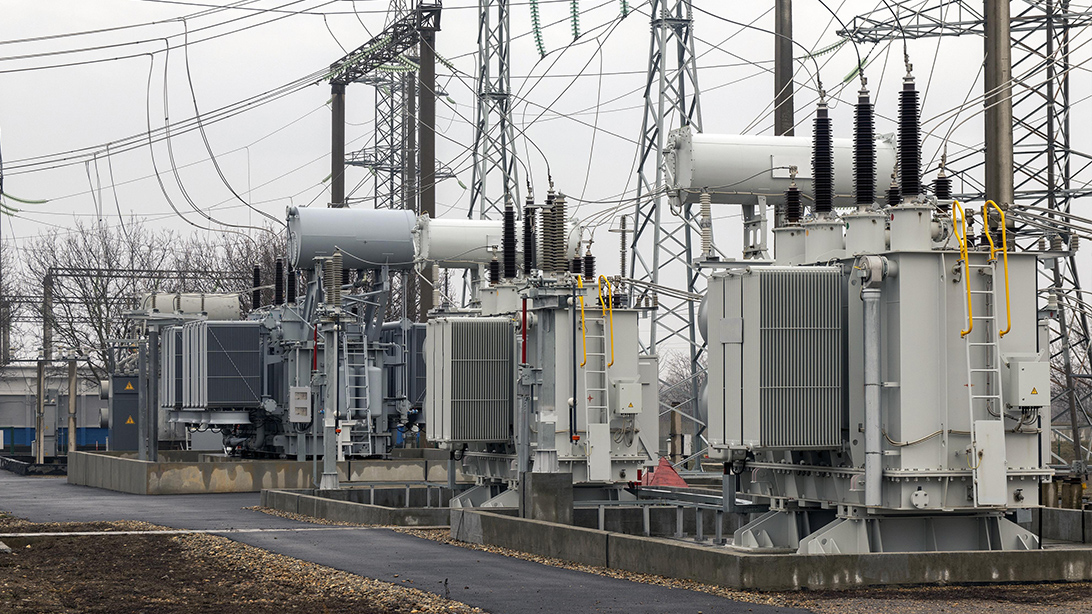
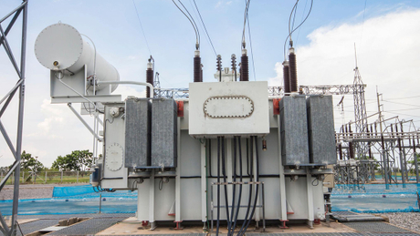
Featured application: an oil-immersed transformer in an industrial distribution system.
Three temperatures are commonly mixed together in technical discussions. Top-oil temperature describes the hottest bulk oil near the upper part of the tank. Average winding temperature is normally derived from resistance measurements during a temperature-rise test. Winding hot-spot temperature refers to the highest local temperature in the winding insulation system. These values are related, but they are not interchangeable.
The hot spot appears where conductor losses, stray losses, oil-flow distribution and insulation geometry combine unfavourably. It may be near a winding end, a transposition, a lead exit or a region with restricted oil circulation. A resistance measurement averages the entire winding. It cannot directly reveal a small local hot zone. That is why a credible thermal assessment combines measured temperature-rise results with a reviewed thermal model and, for appropriate projects, direct fibre-optic measurements.
IEC 60076-2:2011 applies to liquid-immersed transformers, defines temperature-rise requirements and sets out methods for temperature-rise tests. IEC 60076-7:2018 addresses the influence of ambient temperature and loading on operating temperature and insulation life. Project-specific limits, reference ambient conditions and the acceptance method still need to be defined in the specification. A standard number alone does not define the complete thermal duty.
Thermal quantity | What it represents | Main engineering risk | What the purchaser should check |
|---|---|---|---|
Ambient temperature | Cooling medium entering the transformer environment | Design margin disappears when site temperature exceeds the stated basis | Daily and seasonal maxima, enclosure conditions and solar exposure |
Top-oil rise | Bulk oil heating above ambient near the tank top | Oil and upper insulation run hotter; cooling reserve may be inadequate | Test method, stabilization criterion and correction to rated losses |
Average winding rise | Average conductor temperature derived by resistance | Overall winding heating exceeds the guaranteed value | Hot and cold resistance records, timing and extrapolation method |
Hot-spot temperature | Estimated or measured maximum local winding temperature | Accelerated local insulation ageing without a high tank indication | Hot-spot factor, thermal model, sensor arrangement where specified |
Cooling-system margin | Available heat rejection above guaranteed duty | Fans, pumps or dirty radiators cause rapid temperature increase | N-1 cooling philosophy, control stages, alarms and auxiliary supply |
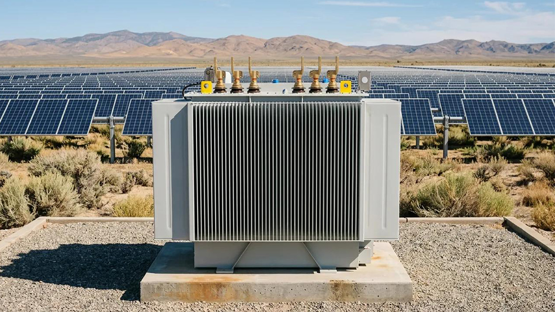
The same rated transformer can face very different thermal duties. A distribution unit serving commercial loads may have a long evening peak. A cement plant transformer may see repeated motor starting and sustained high load. A solar step-up transformer follows irradiance, while a battery energy storage transformer can operate in both power-flow directions with a dispatch profile that changes quickly.
The engineer needs the expected continuous load, peak duration, cyclic pattern, power factor and harmonic content. Harmonic currents increase winding and stray losses, but their effect depends on spectrum and conductor arrangement. Writing “nonlinear load” in a datasheet is not sufficient. For converter-fed loads, we normally ask for the anticipated current spectrum or the converter manufacturer’s harmonic data before finalizing the loss model.
Conductor size cannot be selected from current density alone. Radial and axial dimensions influence leakage field, eddy loss and mechanical strength. Cooling ducts must allow oil to reach the locations that actually generate heat. If a duct is narrowed by insulation build, spacer displacement or excessive clamping deformation, the calculated flow path may not exist in the manufactured winding.
During our design review, we check the relationship between winding loss distribution, duct arrangement and mechanical support. Increasing a duct is not automatically an improvement; it changes winding dimensions, leakage reactance and short-circuit forces. Thermal and mechanical design have to be resolved together. This is also why a late request to change impedance can require another thermal review rather than a simple drawing correction.
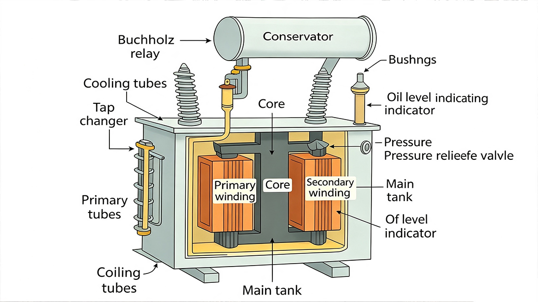
Core, winding and oil-path arrangement determine where heat can accumulate.
Guaranteed load loss is important for efficiency and heat generation, yet total load loss does not show where that heat is concentrated. DC winding loss is distributed broadly. Eddy loss in conductors and stray loss in structural parts can be localized. Leads, winding ends, tank walls, clamps and magnetic shields require attention on larger or high-current designs.
A lower total loss does not automatically prove a lower hot spot. What matters is whether the conductor dimensions, transpositions, shielding and cooling paths are consistent with the calculated loss distribution. For a useful background on how the active part is produced and controlled, review our article on the oil-immersed transformer monitoring and predictive-maintenance guide. When industrial loads drive the design, the project team should also compare the industrial distribution transformer design factors against the load schedule.
Radiator surface area, oil circulation head, pipe dimensions, fan airflow and equipment spacing work together. Adding fans to a weak natural-circulation arrangement may not correct an oil-flow restriction inside the active part. Likewise, a transformer that passes with every fan operating may have little operational resilience if one fan group is unavailable.
One point we clarify early is the relationship between transformer rating and cooling mode: whether rated output is based on ONAN or ONAF, how many cooling stages are provided, which stage is normal, and whether full duty is required with one fan group unavailable. Alarm and trip contacts, motor supply voltage, local/remote selection and automatic control setpoints belong in the interface schedule.
A temperature-rise test is valuable because it checks the assembled unit as a thermal system. It can expose inadequate radiator performance, incorrect fan rotation, control wiring errors, unexpected total losses or a poor temperature margin. It does not reproduce every site condition. The test environment, loss-injection method, cooling equipment and acceptance calculations therefore need to be recorded clearly.
The approved test procedure should identify the applicable standard, connection method, measuring instruments, ambient-temperature measurement, injected losses, cooling configuration, stabilization criterion, shutdown sequence and resistance-measurement timing. If winding temperature is determined from resistance, time is critical after shutdown. A delayed or incomplete series of readings can make extrapolation unreliable.
For multi-cooling-stage units, the procedure should state which rating and cooling mode are being verified. Fan and pump current, operating status and control sequence should be logged. If the project requires a temperature-rise test at a particular tap position, that condition must be agreed before the test because tap position affects losses and may affect the thermal result.
Thermal acceptance must correspond to the specified rating, tap and cooling mode.
A useful FAT report preserves the raw measurements as well as the final calculations. Review ambient readings, oil temperatures, current, voltage, input power, winding resistance, cooling-device status and time stamps. Confirm how measured losses were corrected to the required reference condition and how temperatures were adjusted when test losses differed from the guaranteed losses.
A report that contains only “pass” removes the evidence needed for engineering review. The measured top-oil rise and average winding rise should be traceable to instrument records. If a hot-spot value is calculated, the report should identify the model or hot-spot factor used. If fibre-optic sensors are specified, the sensor locations and valid channels should be agreed before winding manufacture, not after the active part has been assembled.
FAT review item | Common weakness | Engineering check |
|---|---|---|
Ambient measurement | One sensor near a radiator or affected by local airflow | Use the agreed sensor arrangement and review stability across readings |
Injected losses | Test power does not represent the specified total-loss condition | Confirm loss basis and documented correction method |
Cooling mode | All fans operate although the guaranteed rating assumes another stage | Match the tested configuration to the nameplate rating and datasheet |
Hot resistance | Readings start late or too few points are recorded | Review shutdown timing, sequence and extrapolation record |
Hot-spot assessment | A generic factor is quoted without design justification | Request the model basis or approved sensor plan |
Control functions | Thermal result passes but alarms and fan stages are not functionally checked | Witness setpoint simulation, fan rotation and alarm/trip contacts |
Site installation changes airflow. A transformer placed close to a wall, inside a poorly ventilated enclosure or beside another heat source can operate hotter than the FAT unit in open laboratory space. Radiators need clearance for natural convection. Fan discharge should not recirculate hot air. For indoor installations, the room ventilation calculation must include transformer losses at the actual operating duty.
Contamination also matters. Dust, fibres or oil deposits on radiator surfaces reduce heat transfer. A failed fan contactor, blocked cooler, low oil level or incorrect control-mode selection can remove thermal margin without an electrical fault. Commissioning should verify oil level, valve positions, cooler operation, fan direction, temperature instruments and alarm contacts before sustained loading.
Temperature settings must align with the protection philosophy. A winding temperature indicator may include a thermal image based on current, while an electronic monitor may calculate temperature from oil temperature and load. Their readings will not necessarily match a local fibre-optic sensor. The EPC team should define which value is used for alarm, trip, SCADA display and operational trending.
A purchaser does not need to perform the manufacturer’s thermal calculation, but the enquiry must provide the correct boundary conditions. At minimum, send the load schedule, ambient profile, altitude, installation arrangement, enclosure or room ventilation data, harmonic information, cooling redundancy requirement and required alarm/trip interfaces.
State the required tests and witness points in the purchase order. Temperature-rise testing affects laboratory time and production planning, so it should not appear as a late inspection comment. For a broader comparison of transformer technologies and their thermal behavior, use the industrial transformer selection guide.
Input from project team | Why it matters | Procurement wording to confirm |
|---|---|---|
Maximum and cyclic load | Sets continuous heating and recovery periods | Rating basis, overload duty and evaluation period |
Maximum ambient and altitude | Defines available thermal headroom and cooling performance | Design ambient, altitude correction and installation condition |
Harmonic spectrum | Changes winding and stray-loss distribution | Converter data, loss evaluation and any derating |
Cooling redundancy | Determines behavior after fan or pump failure | Rated output by cooling stage and N-1 requirement |
FAT requirement | Controls test scope, schedule and evidence | Applicable standard, witness status, tap, cooling mode and report format |
Monitoring interface | Links thermal condition to operations and protection | Sensors, alarm/trip contacts, protocol and SCADA point list |
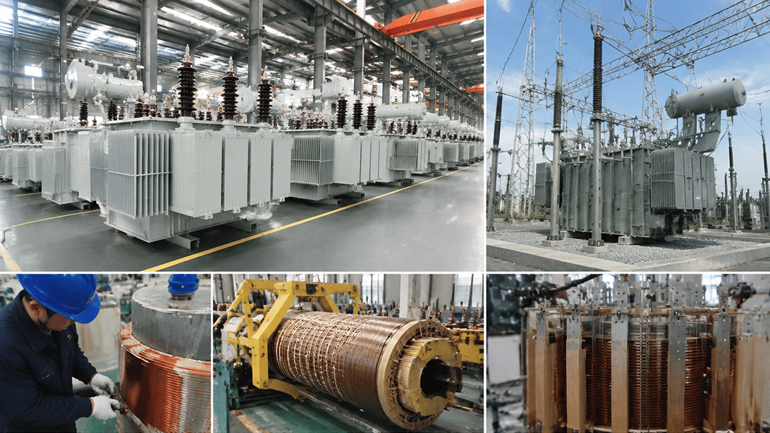
Thermal performance depends on both the approved design and manufacturing consistency.
For an oil-immersed unit, we normally request the datasheet, single-line diagram, load profile, harmonic information, site ambient data, altitude, cooling philosophy and monitoring requirements. Our engineers then check the electromagnetic losses, winding arrangement, internal oil paths, radiator duty, accessory ratings and FAT scope as one package. The objective is not to add equipment without reason. It is to remove uncertainty from the thermal duty before copper is wound and steel is cut.
Zisheng Electric supplies oil-immersed power transformers for substations, distribution and power transformers, dry-type units and related substation equipment. If your project is evaluating transformer hot-spot temperature, send the transformer datasheet, load schedule, ambient conditions, cooling requirement and FAT specification. Our engineering team will review the requirements and respond to project inquiries within 24 hours.