Please Choose Your Language
Views: 0 Author: Zisheng Electric Technical Engineer Publish Time: 2026-08-27 Origin: Zisheng Electric
Short-circuit impedance is often treated as a percentage hidden in the middle of a transformer datasheet. In a real power system, that number affects fault current, voltage drop, parallel loading, protection coordination, and the mechanical forces inside the windings. At Zisheng Electric, we treat transformer short-circuit impedance as a system parameter rather than a value selected by the manufacturer in isolation. If it is too low, the prospective fault current may exceed the switchgear duty. If it is too high, large motor starting and sudden load changes can produce an unacceptable voltage dip.
During FAT, compare the measured impedance with the design guarantee, contractual tolerance, and system fault study.
The impedance voltage, normally shown as uk%, is the percentage of rated voltage required to circulate rated current when one winding is short-circuited and the specified test voltage is applied to the other winding at rated frequency. It contains a resistive component and a reactive component. Leakage reactance normally dominates in medium and large power transformers, but the resistance associated with load loss still matters when engineers assess peak current, temperature, and tap-position performance.
A simple screening calculation for the symmetrical current available at the transformer terminals is:
Ik ≈ In × 100 / uk%
Consider a 2,000 kVA, 0.44 kV transformer with a low-voltage rated current of approximately 2,624 A and an impedance of 6%. If the upstream source is assumed to have infinite fault capacity, the initial symmetrical current is about 43.7 kA. The actual project calculation must add the impedance of the upstream network, cables, lines, and busbars and should follow the method specified by the owner, often IEC 60909. The simplified equation is useful for early screening, not for a final protection-setting report.
Impedance Change | Immediate System Effect | Items to Recheck |
|---|---|---|
Lower uk% | Higher fault current and improved voltage regulation | Breaker interrupting rating, busbar peak withstand, cable thermal duty |
Higher uk% | Lower fault current and greater load-step voltage drop | Motor starting, voltage quality, and parallel load sharing |
Different R/X ratio | Changed peak current and DC component | Protection response and winding mechanical stress |
Different tap position | Changed ratio and impedance | Worst-case operating condition and OLTC range |
A purchase specification that says only “impedance according to IEC” is not enough. The transformer supplier needs the maximum and minimum source fault levels, system voltages, vector group, neutral-earthing method, number of transformers in parallel, load characteristics, and switchgear short-time withstand rating. Mining plants, steel mills, and pumping stations should also provide the large-motor list and starting methods. Solar and battery projects need to explain the converter contribution to fault current because it differs from that of a rotating machine.
If two transformers will operate in parallel, the percentage impedance and voltage-ratio tolerances directly influence load sharing and circulating current. Equal ratings do not automatically guarantee satisfactory parallel operation. The purchase agreement should define the acceptable impedance difference, tap synchronisation philosophy, and the permitted loading when one unit is out of service.
Renewable energy projects should coordinate target impedance with converter behaviour and collector-system impedance.
Short-circuit impedance cannot be adjusted freely after a transformer has been built. Radial winding dimensions, axial height, main insulation clearances, disc arrangement, and the leakage-flux path all influence reactance. When a designer changes one dimension, the team must also review temperature rise, dielectric margin, axial clamping force, and manufacturing tolerance. Reducing an insulation gap only to reach an impedance target can transfer risk into dielectric performance and short-circuit strength.
For an oil-immersed transformer, conductor material, transposition, and lead length influence the resistive component. Winding height and radial spacing have a strong influence on the reactive component. Higher-voltage designs also require a review of tap-winding position and impedance across the full tapping range. Our design review therefore records the principal, maximum, and minimum tap positions instead of relying on one central value.
Altitude, cyclic mining loads, temperature, and insulation corrections must be reviewed together.
IEC 60076-5:2006 addresses a transformer's ability to withstand the effects of external short circuits. It includes thermal calculations and the verification of dynamic withstand by special test or theoretical evaluation. The project documents should identify the applicable edition, fault duration, and fault types. A satisfactory impedance measurement does not by itself prove short-circuit withstand. The impedance test confirms an electrical parameter; the withstand assessment must also cover conductor temperature, axial and radial electromagnetic forces, clamping, and lead support.
For a critical EPC project, the purchaser may request a thermal short-circuit calculation, a summary of axial and radial force checks, a description of winding clamping, and evidence from short-circuit testing or a validated design family. These documents should be reviewed before major materials are released. Where a special short-circuit test is required, the test laboratory, transport plan, test sequence, and post-test measurements must be agreed in advance.
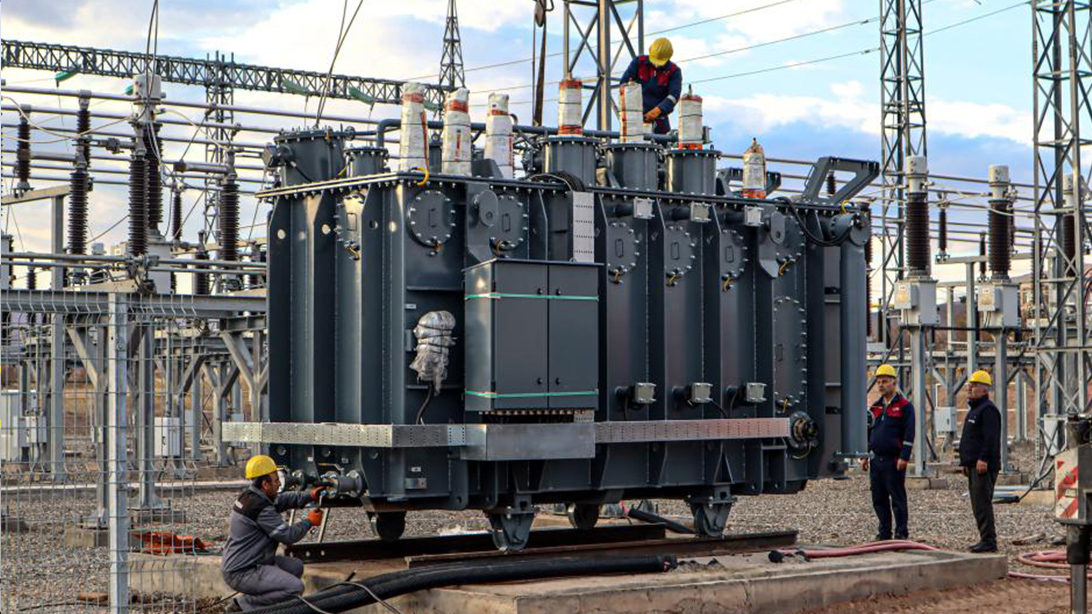
Short-circuit impedance and load loss are normally obtained during the short-circuit test. The connection, instrument accuracy, winding temperature, temperature correction, frequency, and tap position all affect the reported value. A FAT witness should review the raw measurements rather than checking only the word “Pass” on the final report. The measured value must be compared with the guarantee and the contractual tolerance, and the three-phase results should be reviewed for unusual imbalance.
Impedance testing is followed by accessory, nameplate, document, and transport-condition checks.
FAT Check | What to Verify | Common Risk |
|---|---|---|
Tap position | Principal tap and any extreme taps required by the specification | Only the central tap is reported |
Reference temperature | Winding temperature and loss-correction method | Results at different temperatures are compared directly |
Measurement uncertainty | Calibration, CT/PT errors, and test connections | A boundary result is accepted without uncertainty review |
Guarantee comparison | Measured uk% against design, standard, and contract tolerance | Compliance is checked without repeating the system study |
Abnormal pattern | Phase balance and baseline measurements | A possible winding displacement signal is missed |
IEC 60076-1 provides the general requirements for power transformers. The exact tolerances applicable to a project should still be confirmed against the contract and the relevant clauses. If the measured impedance is close to the permitted boundary, the EPC engineer should enter the measured value into the short-circuit model. A formally acceptable value is not an acceptable engineering result if it causes the switchgear duty to be exceeded.
An enforceable impedance clause should identify the guaranteed value, MVA and temperature basis, tap positions, tolerance, parallel-operation requirement, fault duration, maximum system fault level, design-verification documents, and FAT witness points. A project using several transformer ratings should not copy one uk% value across the complete schedule. Each unit should match the bus fault level, protection system, and load behaviour at its own location.
The switchgear data should also be returned to the transformer supplier. A low-voltage board rated 50 kA for one second does not mean the transformer calculation should be allowed to approach 50 kA without margin. The study needs reasonable allowance for network variation, calculation uncertainty, and future expansion. For a 110 kV oil-immersed power transformer or a multi-winding design, the specification should state the impedance between each winding pair and its capacity basis.
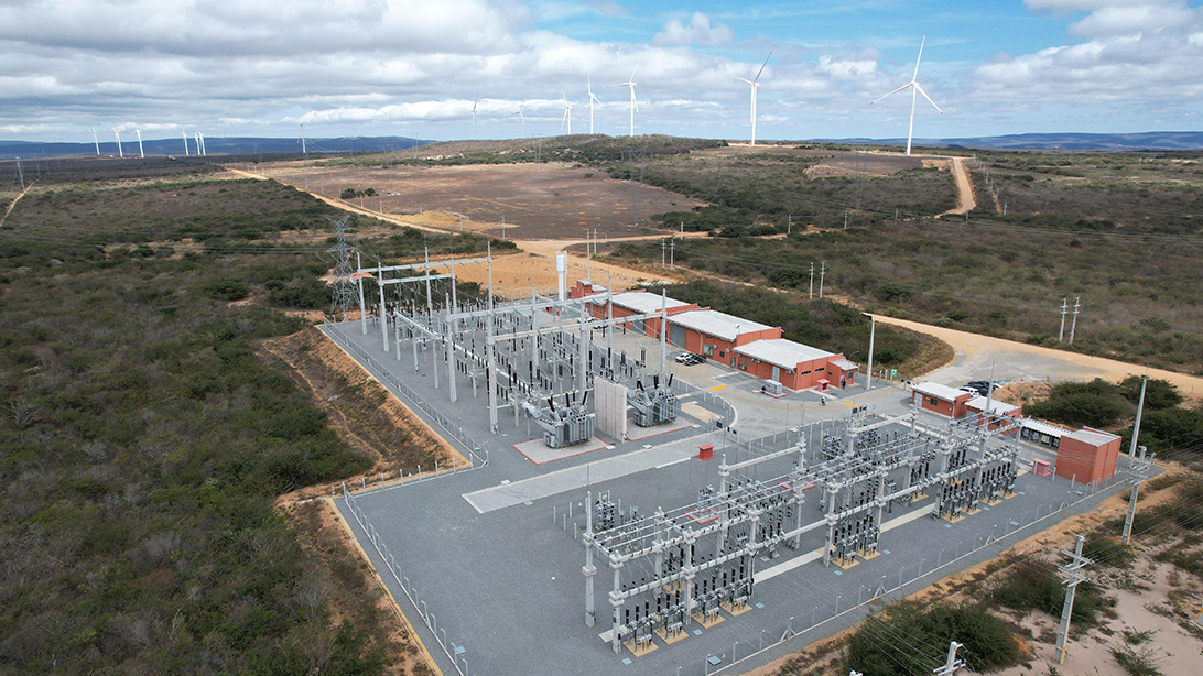
Coastal wind projects require fault level, expansion plan, environment, and equipment ratings to be reviewed together.
One industrial project specified a 2,500 kVA transformer, a 0.4 kV secondary, and 5.5% impedance while the low-voltage switchboard had a 50 kA short-time rating. The infinite-source screening calculation produced a transformer contribution of approximately 65.6 kA. Cable impedance would reduce the value, but the original design had not shown adequate margin.
The clarification was not solved by changing the impedance immediately to 7%. The team reviewed motor-starting voltage, upstream fault capacity, bus length, and the parallel arrangement. The final target balanced fault-current limitation with acceptable load-step performance and was entered into the guaranteed data and FAT tolerance. This type of clarification costs very little before winding manufacture and can require a major redesign after coil dimensions are frozen.
Related design considerations are discussed in our guide to transformer selection for South American renewable energy projects. Procurement teams can also review what South American power markets expect from transformer suppliers.
Keep factory impedance and winding-resistance baselines for comparison after transport and installation.
Short-circuit impedance is useful only when it closes the loop between the transformer, system fault level, protection, switchgear, and load characteristics. Zisheng Electric supplies oil-immersed transformers, power transformers, dry-type transformers, compact substations, and related substation equipment. We can provide technical matching based on project capacity, voltage level, environmental conditions, and technical specifications, with an initial response to inquiries within 24 hours. A single-line diagram, load list, and fault-level data allow our engineers to review the impedance target, FAT scope, and required technical documents during the quotation stage.