Please Choose Your Language
Views: 0 Author: Zisheng Electric Technical Engineer Publish Time: 2026-09-02 Origin: Site
A request for an oil-immersed transformer often includes a tap range before it explains the voltage problem. That reverses the design sequence. From Zisheng Electric's engineering perspective, transformer tap changer selection should start with the incoming supply, the load bus and the conditions under which the ratio must change. A long list of tap positions is not, by itself, a voltage-regulation solution.
The practical decision is whether an occasional adjustment during a planned outage is sufficient, or whether the transformer must regulate while supplying the load. The answer affects winding design, switching duty, controls, maintenance access and the information required at factory acceptance testing. This guide is intended for engineers and technical buyers preparing a transformer specification, not as an instruction for operating energized equipment.
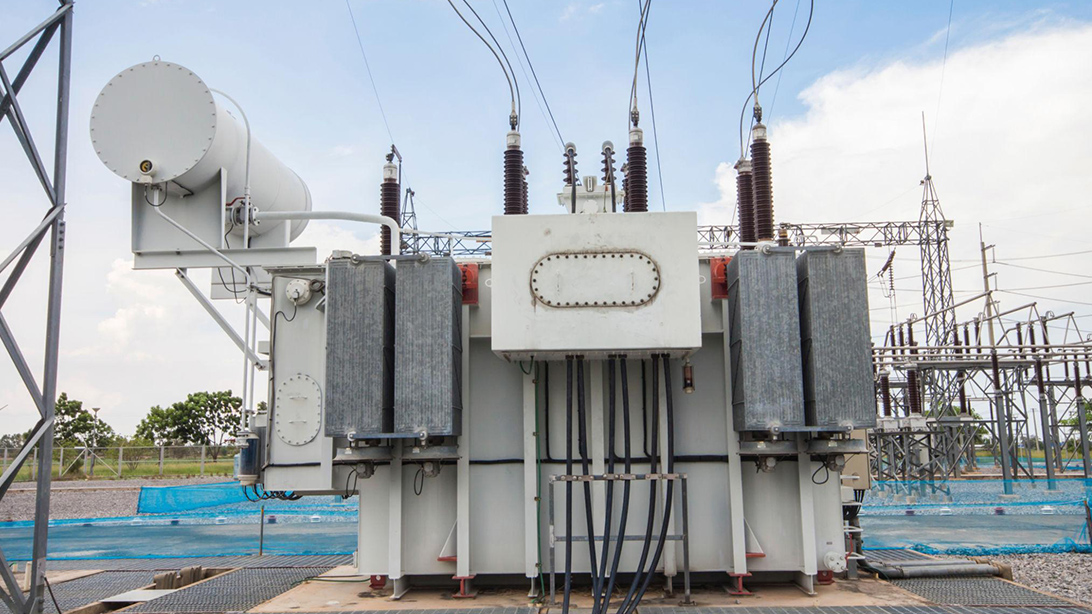
The tap arrangement must be selected with the transformer duty and the voltage required at the supplied bus.
Draw the electrical path: source, incoming feeder, transformer, outgoing circuit and load. Identify where voltage is measured and where it must remain acceptable. A transformer-terminal voltage can look satisfactory while a remote motor sees a much lower voltage through a long feeder. Conversely, increasing transformer output to assist the most distant load can expose nearer equipment to excessive voltage.
Ask for supply-voltage records with operating conditions attached. A minimum and maximum without timestamps can conceal the difference between a sustained supply variation and a brief disturbance. Record normal production, low-load operation, major load changes and any generation export. Keep abnormal fault events separate from normal regulation requirements.
Tap changing is not a universal cure for voltage dips, phase imbalance, harmonics or an undersized feeder. An OLTC control scheme has a deliberate response behavior; it should not chase every short event. If the main concern is motor starting, examine source strength, feeder impedance and the starting method. If the problem is a lasting supply offset, ratio adjustment may be the relevant tool. Define the problem before adding equipment.
For a design review with Zisheng Electric, the useful starting package is a single-line diagram, transformer voltage schedule and a description of when the unacceptable voltage occurs. Those inputs allow an engineering discussion about the required function instead of a comparison based only on component price.
A de-energized tap changer (DETC) changes the selected winding connection with the transformer de-energized. An open secondary breaker alone does not establish that condition: the primary, alternative supplies and possible backfeed must be addressed under the approved isolation procedure. Terms such as “off-load” are easily misunderstood, so specifications should state the permitted operating condition explicitly.
An on-load tap changer (OLTC) is designed to change ratio during energized service within its specified duty. Its switching arrangement manages transfer between adjacent taps. Reinhausen's technical explanation of OLTC operation describes this distinction and the relationship between the tap changer and automatic voltage control.
Project condition | Main risk | Selection check |
|---|---|---|
Voltage setting changes only during planned outages | Buying unnecessary control and maintenance complexity | Assess DETC suitability against the actual voltage envelope and outage procedure. |
Persistent voltage variation must be corrected without interrupting supply | A fixed operating tap cannot maintain the required bus range | Assess OLTC duty, sensing location and control performance together. |
The specification says only “off-load taps” | An operator may interpret no load as safe to switch while energized | Use an explicit de-energized operating requirement and manufacturer instructions. |
Frequent short voltage disturbances dominate | Repeated switching without solving the cause | Investigate network and load behavior before choosing faster or wider tap regulation. |
Transformers may operate in parallel | Uncoordinated ratio changes can create circulating current | Include a coordinated regulation philosophy and compatibility study. |
For comparison, the S11 non-excitation voltage-regulating transformer represents a product route to investigate where de-energized adjustment is appropriate. The selected order still needs a confirmed tap schedule and operating procedure. A catalogue label does not replace those documents.
State which winding is tapped, its principal-tap rated voltage, the step size and the usable end positions. Also define whether the transformer maintains its rated power across all taps or has declared restrictions. Two quotations can both say “plus or minus five percent” while using different voltage bases, position numbering or rating assumptions.
Consider an idealized transformer with a principal ratio of 11 kV to 0.4 kV and taps on the HV winding. At an actual 11 kV supply, selecting a tap rated 11.55 kV gives an approximate no-load secondary voltage of 11 / 11.55 × 400 = 381 V. Selecting a tap rated 10.45 kV gives approximately 421 V. These are illustrative calculations, not recommended settings or guaranteed loaded voltages.
The important point is direction: adding effective HV turns reduces secondary voltage for an unchanged applied HV voltage. A “raise” command can refer to regulated output voltage, while a tap number or percentage can describe the tapped winding. Do not assume that increasing the displayed position number raises the load voltage.
Use the approved connection diagram and tap table to define every position. The design calculation must then include the actual source range, transformer voltage drop and outgoing feeder drop. Check the high-supply, light-load condition as well as the low-supply, heavy-load condition. A setting selected only to improve the latter may create an unacceptable condition in the former.
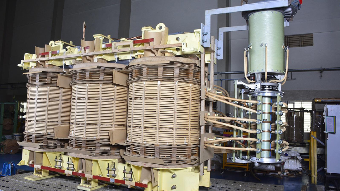
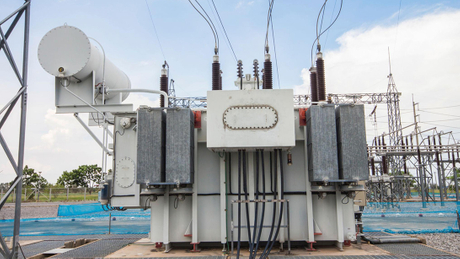
Tap leads, winding insulation and switching equipment form one coordinated design.
Transformer capacity is only a starting input for the component selection. The winding arrangement determines the current passing through the selected contacts and the voltage between the relevant taps. A connection at a neutral end and a connection elsewhere in the winding do not automatically impose the same insulation duty.
For a balanced three-phase winding, line current can be estimated from apparent power divided by square root of three times line-to-line voltage. That is not permission to equate line current with every internal contact current. The winding connection, regulating circuit and tap-changer arrangement must be considered by the designer.
Review the maximum through-current, step voltage, insulation requirements and specified overload duty as a coordinated selection. Where nonsinusoidal currents or unusual operating cycles are expected, provide those conditions to the component supplier. Do not extrapolate a catalogue rating beyond its stated application conditions.
The principal tap is not always the most demanding operating point. Ask the manufacturer to identify the limiting tap conditions for current, heating and magnetic design. Applied voltage, frequency and effective turns influence core flux; a ratio adjustment must stay within the transformer's approved operating envelope. More range is therefore not automatically better.
The physical layout also matters. Tap leads need controlled routing, insulation clearances and mechanical support. A late change in regulating range may require winding or lead-layout changes, not merely a different nameplate. Freeze the electrical schedule before treating the tank arrangement and manufacturing drawings as final.
An OLTC and a voltage controller have different jobs. The switching equipment changes the ratio; the controller decides when a change is required. A complete specification identifies the measurement source, voltage-transformer ratio, regulated point, setpoint, deadband, time delays, position limits and local or remote authority.
A deadband that is too narrow for the measurement quality and normal system variation can cause unnecessary operations. A delay that is poorly coordinated with other regulators can produce competing corrections. Set these values through the project study and the equipment instructions rather than copying another installation.
Define behavior for loss of voltage sensing, loss of drive power, an incomplete operation, contradictory commands and position-feedback failure. The correct response may be blocking, alarm or another engineered action depending on the scheme. The requirement must be explicit enough to test. Avoid the assumption that loss of communication should trigger a move to a supposedly safe tap.
For larger applications, the 110 kV and 115 kV power transformer range provides a starting point for project-specific tap and control discussions. Confirm the proposed arrangement in the order documentation, including the drive and controller scope; do not assume that optional equipment is included in every supply.
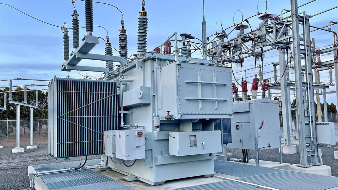
Voltage sensing, drive supplies and operating controls need to match the installed substation arrangement.
If a bus tie can connect two transformer secondaries, the regulation philosophy must account for that operating mode. Matching nameplate ratios is not enough. Compatible vector groups, tap relationships, impedances and load sharing need an engineering review. Independent controllers attempting to hold slightly different voltages can work against each other.
The control designer should define how the units coordinate, how a unit entering or leaving parallel service is handled, and what happens when position information is unavailable. These are selection inputs because they influence the required controller functions and signals.
Where power flow can reverse, identify the actual import and export modes. Any line-drop compensation or directional control function must be reviewed for those modes. Do not assume that a control arrangement developed for one-way industrial supply will behave correctly in a generating installation. This is a project-study question, not something a generic tap percentage can settle.
The FAT should demonstrate that the manufactured assembly matches the approved selection. That means linking the transformer serial number, winding diagram, tap schedule, position indication and applicable control drawings. A successful component certificate alone does not prove that the complete transformer is wired and indicated correctly.
Design input | Why it matters | Procurement or FAT check |
|---|---|---|
Tap schedule and winding diagram | Define the expected electrical result at each position | Compare position marking, measured ratio and approved sequence. |
Maximum duty at relevant taps | Establishes component and winding suitability | Obtain the selection record, stated rating basis and any restrictions. |
Drive supply and command logic | Determines whether commands produce the intended operation | Verify specified local and remote functions with the approved safe procedure. |
Position feedback and end limits | Incorrect indication can mislead operators | Record agreement between mechanism position, local indication and remote signals. |
Voltage sensing and controller settings | Incorrect measurement or logic produces incorrect regulation | Verify the documented response using an approved simulation or secondary-injection method. |
Final operating position and documentation | Factory and site teams need one reference condition | Record final position, drawings, settings, outstanding items and release authorization. |
The ratio and vector-group test guide explains the electrical checks in more detail. For contact-path and winding results, the winding-resistance FAT guide is a related reference. These tests answer different questions and should not be substituted for each other.
Agree the actual test scope and acceptance criteria before the witness date. A low-voltage functional check of a drive is not a demonstration of full switching-duty capability. Conversely, type-test evidence for a component does not replace verification of the installed wiring, indicators and controls. Keep those evidence categories separate in the inspection plan.
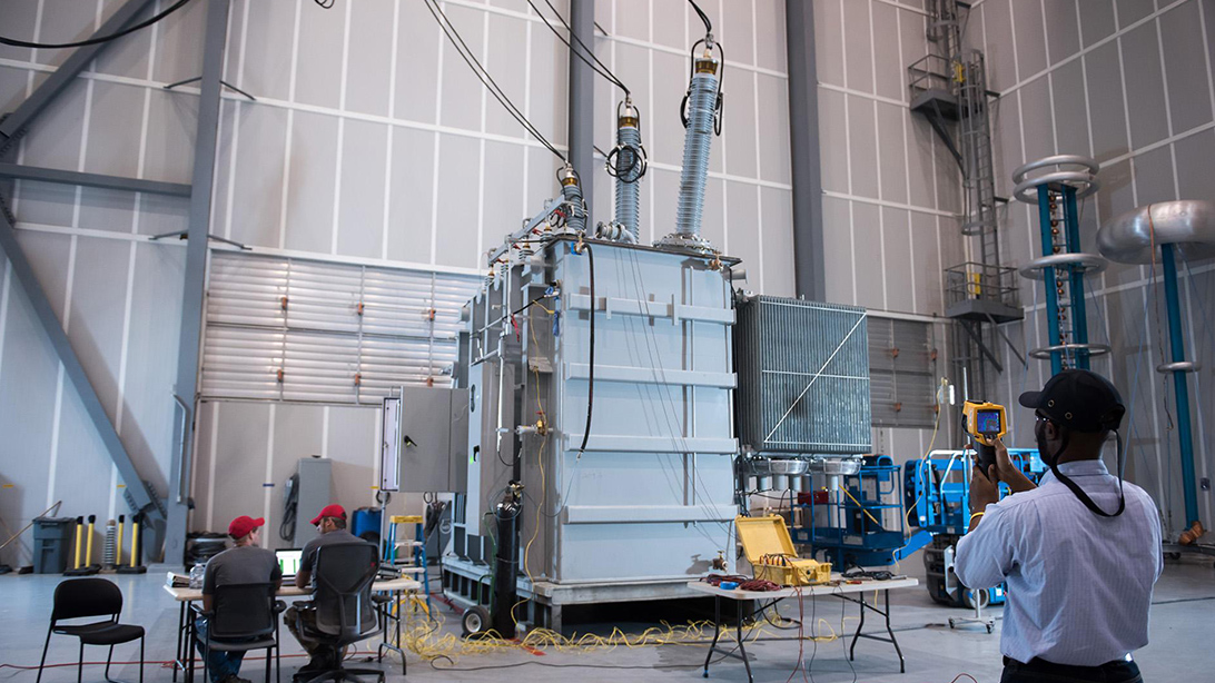
Factory verification should connect the approved tap schedule to measured ratios and operating indications.
IEC 60214-1:2014 addresses tap-changer performance requirements and test methods, including on-load and de-energized types and their drive mechanisms. IEC/IEEE 60214-2:2019 provides application guidelines for selection and use. Specify the contractual editions and applicable requirements; a general reference to “IEC compliant” leaves too much unresolved.
The component instructions remain essential for installation, operation and maintenance. Ask for inspection intervals, operation-count criteria where applicable, access requirements and the exact consumables or service parts. Do not assume vacuum switching makes every part of an OLTC maintenance-free. The drive, seals, controls and any separate fluid system still have defined requirements.
Maintenance access must be physically possible after installation. Check cover removal, drive access, oil-handling provisions where relevant and the clearance needed for the specified service procedure. These practical details belong in the design review, when they can still be accommodated without rework.
For transformer tap changer selection, send the single-line diagram, transformer datasheet, supply-voltage records, load schedule, proposed tap range and required operating modes. Include parallel-operation or reverse-power conditions and the project control specification where applicable.
Zisheng Electric can provide technical matching for oil-immersed distribution and power transformers based on project capacity, voltage level, environmental conditions and technical specifications. Our engineering team will review the requirements and respond to project inquiries within 24 hours.