Please Choose Your Language
Views: 0 Author: Site Editor Publish Time: 2026-08-26 Origin: Site
For overseas EPC projects and power infrastructure projects, transformer manufacturing quality directly affects reliable operation over decades of service. From raw material selection, core manufacturing, and winding production to the final Factory Acceptance Test (FAT), every stage can influence the transformer’s performance.
As a technical engineer at Zisheng Electric, I am often asked the same question by procurement teams and EPC clients: How is the quality of a transformer actually guaranteed?
The answer is straightforward — from the day the raw materials enter the factory to the final factory testing before shipment, every stage is subject to strict quality control. Below, I will break down the entire manufacturing process step by step.
The service life and reliability of a transformer depend heavily on the quality of its raw materials. Electrical steel laminations are the key material used in the transformer core. We use high-permeability grain-oriented electrical steel (GOES) and require suppliers to provide material samples together with magnetic performance data for the specified grade before procurement.
After the materials arrive at our factory, they are re-inspected according to the project technical specifications and applicable material standards. For export projects, the materials must also comply with any standards specifically required by the customer.
Key inspection items include magnetic flux density, core loss, thickness tolerance, and surface quality. The surface of the electrical steel must be flat and clean, with no defects such as rust, coating blistering, creases, or cracks.
The winding conductors are made of oxygen-free copper or aluminum. Upon arrival, the supplier’s qualifications and quality certificates are verified, and the chemical composition, mechanical properties, and electrical conductivity of the conductor materials are reviewed.
Insulating materials such as pressboard and insulating oil are inspected in accordance with the applicable standards. Mineral insulating oil complies with GB/T 2536-2024, while export projects are also required to meet IEC 60296. Electrical pressboard complies with GB/T 19264 and IEC 60641-3-1. For Class F/H insulation materials, corresponding certificates confirming their thermal performance must be provided.
All raw materials may only be accepted into warehouse storage after they have passed the incoming inspection and a qualified incoming material inspection report has been issued.
The core forms the transformer’s magnetic circuit, and the core stacking process directly affects no-load losses and noise levels.
The electrical steel sheets first undergo slitting and cross-cutting, during which sheet length, width, cutting angle, and burr height are carefully controlled. During stacking, operators assemble the laminations step by step according to the design drawings. After each stacking stage, key dimensions such as the diagonal length, limb height, distance between limbs, yoke length, and stacking thickness are measured to ensure that dimensional tolerances meet the process requirements.
The window widths on both sides of the core are also checked to ensure equal spacing and maintain a symmetrical magnetic circuit structure.
The cores of large transformers may consist of tens of thousands, or even more than one hundred thousand, electrical steel laminations, each only 0.18 mm to 0.27 mm thick. During stacking, strict control is required over the joint gap, flatness, compactness, and symmetry. These factors directly affect magnetic circuit efficiency as well as operating performance such as transformer no-load losses and noise.
The winding is the electrical circuit section of the transformer, and the quality of the winding process directly affects its load-carrying capability and short-circuit withstand strength.
Winding is carried out on high-speed winding machines. The conductors are mechanically tensioned, with the tension maintained at a constant level throughout the process. During winding, it is essential to ensure the correct number of turns, orderly conductor arrangement, and proper interlayer insulation.
The conductor surface must be smooth and free from defects such as burrs, scratches, or surface laps.
After winding is completed, the winding undergoes insulation treatment to improve both its dielectric performance and mechanical strength.
For rectangular conductors, inconsistent corner radii can result in differences in the effective conductor cross-sectional area and poor fitting between adjacent turns. This may further increase the risk of three-phase DC resistance imbalance.
After the core and windings are completed, the transformer enters the active part assembly stage. The windings are fitted onto the core limbs, followed by the installation of insulation components and lead connections. The assembled active part then undergoes constant-pressure drying.
After drying, the overall dimensions and clamping condition of the active part are checked and corrected as necessary. Any dust, particles, or other contaminants on the surface are carefully removed before final tanking.
The transformer tank is fabricated from high-quality steel plates by welding. X-ray radiographic inspection is carried out on critical welds to detect and eliminate welding defects and minimize the risk of oil leakage.
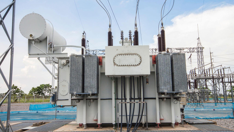
The completed active part is then lifted into the tank, and the internal leads are connected to the bushings. External components and accessories, including bushings, radiators, and the conservator, are installed in sequence. The transformer then proceeds to subsequent processes such as vacuum oil filling.
One of the most critical processes in manufacturing an oil-immersed transformer is vacuum oil filling.
Before oil filling begins, the transformer tank is evacuated to remove residual air from inside the tank and from the pores of the insulation materials. The required vacuum level is determined according to the transformer’s voltage class and rated capacity. This process helps reduce potential insulation problems caused by trapped gases and moisture. For transformers rated at 220 kV and above, the vacuum treatment requirements are more stringent.
For high-voltage and higher-voltage-class transformers, the specified vacuum level is maintained throughout the entire oil-filling process. Medium- and low-voltage transformers are vacuum-filled in accordance with the applicable manufacturing procedures.
The insulating oil temperature during filling is controlled between 55°C and 65°C. The oil-filling rate is also strictly controlled and should not be excessively high, as excessive oil flow may cause static electrification. For medium- and large-capacity transformers, the filling rate is generally kept below 100 L/min.
After oil filling is completed, the transformer undergoes pressurized settling followed by a leak-tightness inspection. According to the project technical specifications, a specified pressure may be applied to the conservator—for example, 30 kPa for 24 hours. The transformer is considered acceptable if no oil leakage is detected at the tank, flanges, welds, or other sealing points. The applied test pressure must not exceed the design pressure limit of the transformer tank.
Every transformer must pass a complete set of routine tests before leaving the factory. The table below summarizes the main test items and typical acceptance criteria, with testing carried out in accordance with the relevant IEC standards.
Test Item | Test Method | Standard Requirement / Typical Value | Remarks |
|---|---|---|---|
Winding DC Resistance Measurement | Double-arm bridge or DC resistance tester | Three-phase unbalance ≤2% for line-to-line values and ≤4% for phase values | Results are converted to the same reference temperature for comparison. IEC does not specify a universally fixed limit; these values are commonly used in industry and project specifications. |
Voltage Ratio Measurement and Vector Group Verification | Transformer turns ratio bridge or TTR tester | Rated tap deviation ≤±0.5%; other taps ≤±1.0% | Vector group is verified at the same time. Tolerances follow IEC 60076-1, while project specifications may impose stricter requirements. |
Insulation Resistance Measurement | 2500 V megohmmeter or insulation resistance tester | Not less than 70% of the factory reference value; absorption ratio ≥1.3 at 10°C–30°C | Measurements are taken between windings and earth and between individual windings. The absorption ratio is mainly meaningful for larger oil-immersed transformers and has limited reference value for smaller units. |
No-Load Loss and No-Load Current | Power analyzer at rated voltage | No-load loss ≤ guaranteed value +15%; no-load current ≤ guaranteed value +30% | Voltage waveform distortion should be <3%. For 60 Hz projects, testing must be carried out directly at 60 Hz rather than converted from 50 Hz test data. |
Short-Circuit Impedance and Load Loss | Short-circuit test at rated current | Short-circuit impedance deviation ≤±5%; load loss ≤ guaranteed value +15% | Results are corrected to the specified reference temperature, typically 75°C for Class A oil-immersed transformers and 120°C for Class F insulation systems. |
Separate-Source AC Withstand Voltage Test | Specified power-frequency voltage applied to the tested winding for 1 minute | In accordance with IEC 60076-3, with no breakdown or flashover | Non-tested windings must be properly grounded. |
Induced AC Withstand Voltage Test | Increased-frequency test, typically at twice the rated frequency | In accordance with IEC 60076-3, with no insulation breakdown during the specified test duration | Used to verify turn-to-turn and layer-to-layer insulation performance. |
Partial Discharge Measurement | High-frequency partial discharge measuring system at approximately 1.1–1.5 × Um | ≤100 pC for 110 kV and above; ≤200 pC for 35 kV and below | Used to identify potential insulation defects. It may be conducted as a type or special test, while some projects require partial discharge testing on every unit before shipment. |
Insulating Oil Breakdown Voltage and Dielectric Dissipation Factor | Physical and chemical analysis of oil samples | Breakdown voltage ≥40 kV; dielectric dissipation factor at 90°C ≤0.5% | Export projects generally follow IEC 60296. Sampling or full inspection depends on transformer voltage class and project requirements. |
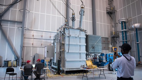
All test data are fully recorded and retained, and formal factory test reports and type test reports are issued. Purchasers or EPC clients may also send representatives to the factory for manufacturing supervision, inspection, and test witnessing.
This is the complete process a transformer goes through, from the arrival of raw materials to final factory release.
For purchasers, complete manufacturing records and test data are important evidence when evaluating a supplier’s actual technical capability. As a procurement team or EPC contractor, the focus should not be limited to the initial purchase price of the equipment. The more important question is whether the transformer can continue operating reliably after 10 or 20 years in service.
That long-term reliability is built into every detail of the manufacturing process — from raw material control and production workmanship to final factory testing.
Zisheng Electric has extensive experience supporting projects across the Middle East, Africa, and South America, providing EPC contractors, project owners, and engineering consultants with transformer selection, technical documentation, and manufacturing coordination services.
Our product range includes oil-immersed transformers, pad-mounted transformers, pole-mounted transformers, dry-type transformers, and other power distribution equipment. We support IEC-compliant design, Factory Acceptance Testing (FAT), and third-party inspection and supervision.